Installation Components Required
- Waterloo Emitter™
- NPT riser pipe or suspension line with threaded top cap
- 1/4" LDPE tubing (supply and vent lines)
- Oxygen Supply - Medical grade or Extra-dry oxygen
- Oxygen regulator for supply tank
- Reducer regulator and gauge to allow setting pressures at:
- 2 - 20 psi (silicone tubing)
- 10 - 100 psi (LDPE tubing)
- Tubing manifold if more than one Emitter is to be supplied from the same oxygen tank
- Shut-off valve or needle valve for system purging
- To improve oxygen delivery, consider using larger diameter tubing to supply oxygen to each wellhead when more than 10 Waterloo Emitters are connected in series.
The Waterloo Emitter™ is based on the principle of diffusion (US Patent: 5,605,634), therefore groundwater gases (e.g. CO2, CH4, etc.) can back-diffuse across the tubing membrane. This lowers the partial pressure of the remediation gas (e.g. oxygen), causing the performance of the units to drop-off over time. To mitigate this effect, it is necessary to periodically purge the units of these groundwater gases.
Purging the units is simple and can be accomplished in either of the following ways. The gas line configuration can utilize an On/Off valve, to allow manual purging from time to time. This shut-off valve will need to be opened once per week to allow a flow of gas for 5-10 seconds to purge the units of any accumulated groundwater gases.
Alternatively, the system vent line can be configured utilizing an adjustable flow needle valve. This allows a small flow (1-2 ml/min) of remediation gas constantly through the units, to passively purge the system. A constant purge of gas at 1-2 ml/min does not significantly increase overall gas usage. See Figure 1 for gas supply connection guidelines.
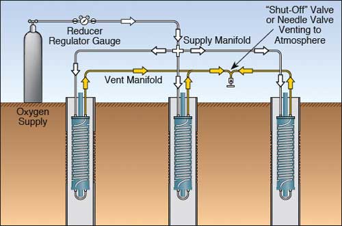
Figure 1
Multiple Well Installation with Single Supply
- Visually inspect parts for any damage. Each container includes: 1 Waterloo Emitter unit, 4 x 1/4" (6.4 mm) brass compression fitting nuts with ferrules, 1 short length of LDPE tubing loop and 4 spare plastic clamps. Note that 5.8" (147 mm) Emitters and all Emitters using LDPE tubing do not use plastic clamps.
- Select one end of Waterloo Emitter to be the "bottom end" (i.e. the end that will reside deepest in the treatment well).
- Attach 1/4" (6.4 mm) LDPE tubing loop with supplied 1/4" (6.4 mm) brass compression fittings to be the "bottom end" of the unit. (See Figure 2).
- a. If sampling within Emitter wells is required, attach lengths of PVC riser casing. Note that 1.8" (45.7 mm) Emitters use 3/8" NPT Pipe, 3.8" (96.5 mm) Emitters use 1/2" NPT pipe, and 5.8" (147 mm) use 1.25" NPT pipe, as the riser casing.
b. If sampling within the Waterloo Emitter well is NOT required, attach a suspension line through a small hole drilled into a threaded top cap. Knot the cord so it will not pull through the hole. (See Figure 3). - Attach appropriate lengths of 1/4" (6.4 mm) O.D. polyethylene tubing to extend from the top end 1/4" (6.4 mm) fittings on the Emitter 5 (See Figure 3) to the gas supply and vent manifolds.
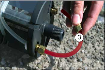
Figure 2
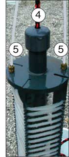
Figure 3
- Make sure the shut-off valve or needle valve is closed and make sure all other valves are open. Set pressure regulator to the appropriate operating pressure.
MAXIMUM PRESSURE
Set Pressure Relief Valve at:
LDPE Tubing: 100 psi, Silicone Tubing: 20 psi
DAMAGE TO TUBING WILL OCCUR IF MAXIMUM PRESSURES ARE EXCEEDED.
- Prior to submersing the units in the treatment wells, while the system is under pressure, leak test all fittings (either submerse the units in a water bath or soap test the connections). Adjust fittings as necessary to eliminate any leaks prior to installation.
- Lower the unit to desired depth within the screened treatment well and secure suspension line or riser pipe at the well head.
- While NOT exceeding above specified maximum pressures, adjust pressure regulator to desired operating pressure. For systems utilizing a constant purge of the vent line, adjust the needle valve to allow 1-2 ml/min of flow.
See oxygen consumption estimates.