Straddle Packer: Installation & Inflation
Model 800 Pneumatic Packers are inflated with air via 1/4" (6.4 mm) OD tubing extending from the packer to the surface. A hand pump with a gauge may be used to inflate the packer. Please read through these instructions fully before proceeding.
Straddle Packer: Assembly & Tubing Connection
- To assemble the Straddle Packer system, connect the lower and upper packers with a suitable length of screen or perforated pipe (1/2" NPT for 1.8" (46 mm) or 1" NPT for 3.9" (99 mm) packers).
To connect 3.9" (99 mm) packers, you will also need to use a PVC bushing, and the NPTF coupling that comes with the perforated straddle pipe (see diagram). - Attach a length of 1/4" 6.4 mm) inflation line between the top of the lower packer and the bottom of the upper packer. Simply push the tubing onto the stainless steel barb fittings.
Note:
Use an awl to open the very tip of the tubing, or heat the tubing to help push it completely over all the barbs.
- Cut an appropriate length of 1/4" (6.4 mm) O.D. tubing to extend from the top packer to the surface with enough slack to allow ease of inflation.
- Push the top end of the inflation tubing into the push fitting on the inflation valve (to release tubing push down on both sides of the fitting and pull tubing out).
- Connect the other end of the inflation tubing to the packer. Push the tubing onto the stainless steel barb fitting. Check the connection by pulling firmly on the tubing. It should not pull off of the fitting.
- The system is now complete and should be installed by connecting the appropriate riser pipe and lowering the system into the well.
- If a riser pipe is not used, then hang the packer with a wireline to suspend at the appropriate depth. A safety cable should be attached to the eyebolt on the packer to allow securing at surface, and between each packer. The Solinst Tag Line can be used for this purpose.
Note:
The lower packer of the Straddle Packer system has only one inflation line fitting.
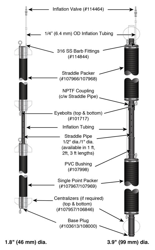
Standard Straddle Packer Setup with Inflation Lines
Note:
Figures A and B illustrate centralizer installation for both Single Point and Straddle Packers. For packer specifications, borehole sizes and required inflation pressures, please refer to the charts.
800 Packer Centralizer Installation (Single Point and Straddle Packers) – trim to fit borehole
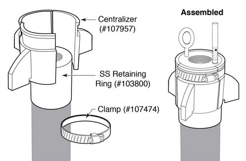
Figure A - 1.8" (46 mm) Centralizer Assembly
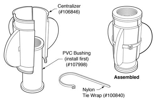
Figure B - 3.9" (99 mm) Centralizer Assembly


