Water Level Meter: Operating Instructions

Equipment Check
- Turn sensitivity dial fully clockwise.
- Clockwise rotation of sensitivity dial turns meter on and increases sensitivity.
- Always set switch to highest sensitivity position, then decrease if necessary.
- Depress the Battery Test button to test the battery and main circuitry (does not test the tape or probe).
- Submerse the probe in tap water. This completes the circuit and activates the buzzer and light.
Notes:
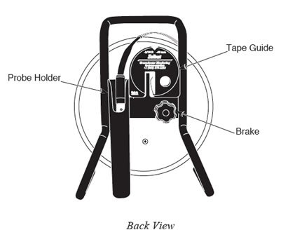
The Tape Guide

The Tape Guide has been designed to:
- Improve accuracy when reading water levels,
- Easily obtain repeatable measurements,
- Prevent tape being cut by well casing,
- Allow the tape and probe to hang straight from the side of the well.
- Fit the small end of the Tape Guide onto the edge of well casing 2" (50 mm) diameter or larger.
- For small reels only, insert the leg of the Water Level Meter into the hole on the Tape Guide and rest the Water Level Meter on the side of the well casing. (See diagram below).
- To store the Tape Guide, simply clip it onto the support bracket located on the back of the Water Level Meter.

Water Level Measurements
- The 101 Water Level Meter P7 Probe zero measurement point is located near the tip of the probe.
- For ease of operation the Tape Guide can be used to support the Water Level Meter. (See diagram above).
- Feed the tape into and out of the well using the groove in the top of the Tape Guide. The light and buzzer activate when the black Delrin tip is submerged and the zero point is reached. To ensure accuracy, lower and raise the probe a few times and then record the depth measurement from the tape at the top of the well.
- When using the Tape Guide, the measuring point is offset from the top of casing. To adjust your measurements to the top of the casing, simply subtract the amount indicated on the front of the Tape Guide (i.e. 6 cm or 2/10 ft).