
Linda M. McGlochIin, R.G. EARTH TECH Colton, CA 92324
ABSTRACT
Much has been written about the advantages of multilevel (multiport) monitoring wells over clustered or nested monitoring wells; however, there is little published information that provides helpful hints and "dos and don'ts" for planning successful multilevel well projects. This paper discusses the differences in both design and construction techniques between conventional monitoring wells and multilevel wells, with emphasis on avoiding some of the pitfalls that can occur with deep multilevel monitoring wells. Numerous methods and procedures are discussed, ranging from using downhole video logs for accurate packer placement to selecting the appropriate size sand for the bentonite/sand mix annular seal.
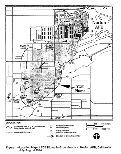
The author refers to a project at Norton AFB in San Bernardino, California, where EARTH TECH, while under contract to the United States Air Force, recently installed eight multilevel wells, each with a Waterloo Multilevel Groundwater Monitoring System. The systems were installed to depths of 400 to 700 feet to characterize the vertical and lateral extent of a plume of trichloroethene (TCE). The off-base portion of the TCE plume at Norton AFB has gained national attention because it threatens 26 municipal wells that provide a major percentage of the domestic water supply for the City of Riverside. Because of the contamination, which resulted from the spillage of TCE during aircraft maintenance activities from 1942 to 1966, Norton AFB has been named a National Priorities List (NPL) site.
According to manufacturer, Solinst Canada Ltd, this is the largest group of deep Waterloo Multilevel systems ever installed in the United States and the first used for a remedial investigation of groundwater contamination on an Air Force installation. Not including those systems installed by EARTH TECH, only 13 Waterloo Multilevel systems had been previously installed in the United States and Canada to depths greater than 400 feet.
INTRODUCTION
In recent years, there have been significant advances in the development of groundwater sampling systems. Most notable are those sampling systems that enable the collection of multiple depth-discrete groundwater samples from a single monitoring well. Prior to the development of these "multilevel" groundwater sampling systems, nested or clustered monitoring wells were typically used to characterize vertical variations in water quality in ail. aquifer. However, clustered and nested monitoring wells, particularly in deep aquifers, can be costly in both initial well construction and follow-on sampling.
There are several commercially available groundwater sampling systems for multiple screened monitoring wells. This paper focuses more specifically on the successful use of the Waterloo Multilevel Groundwater Monitoring System, manufactured by Solinst Canada Ltd., at Norton Air Force Base (AFB), California. Helpful hints and "dos and don'ts" which are discussed herein, particularly in regard to multilevel well design, field activity planning, and system installation, might also be applicable to investigations involving the installation of other manufacturers' groundwater sampling systems.
Background
Norton AFB is located in the north-central portion of the San Bernardino Valley area, approximately 65 miles east of Los Angeles. The San Bernardino Valley is one of the major alluvial valleys of the South Coastal Basin of California. The base lies on an alluvial terrace on the north bank of the Santa Ana River, about 2 miles southeast of the city of San Bernardino. Groundwater beneath Norton AFB is contained in three aquifers (upper, middle, and lower) and is part of the Bunker Hill Groundwater Basin.
Norton AFB, which has been closed to military operations since March 1994, was formerly used as an aircraft repair center for the United States Air Force. Military aircraft operations began as early as 1942 with the San Bernardino Air Depot and have since included such activities as an engine maintenance center for cargo and fighter aircraft. TCE spillage, which resulted from aircraft repair activities, occurred as late as 1966.
Potential contamination at Norton AFB has been investigated since 1982 as part of the U.S. Air Force's Installation Restoration Program ('RP). These previous studies identified a wide area of TCE contamination in the groundwater beneath the base. Trace concentrations of TCB and minor amounts of cis-1,2 dichloroethene were also detected in municipal water supply wells located near the base's southwest boundary along the Santa Ma River. Environmental investigations at Norton AFB identified over 20 sites with potential environmental contamination; however, the primary source for the TCE contamination in groundwater was determined to be the soil in the vicinity of a large aircraft hangar and passenger terminal in the Central Base Area (CBA). For this reason, Norton AFB was placed on the NPL of hazardous waste sites in 1987.
Characterization of the TCE Plume
In 1992, the Air Force Center for Environmental Excellence (AFCEE), located at Brooks AFB in Texas, contracted with EARTH TECH (The Earth Technology Corporation) to participate in a Remedial Investigation (RI) related study for the characterization of the off-base portion of the TCE plume. The TCE plume, which had migrated at least 1/2 mile off base, was threatening production wells owned by the City of Riverside. Phase I of the off-base TCE plume investigation (EARTH TECH, 1992) involved the drilling and installation of seven clusters of monitoring wells midway between the City of Riverside production well fields and the southwestern base boundary. Each cluster contained four monitoring wells approximately 100, 150, 200, and 250 feet in depth. Groundwater samples from these monitoring wells indicated that the TCE plume had migrated deeper in the aquifer and farther off base than originally anticipated. With concurrence from the U.S. EPA, California
Department of Toxic Substances Control, and the California Regional Water Quality Control Board, Norton AFB and EARTH TECH pushed forward an aggressive schedule to complete the characterization of the off-base portion of the TCE plume.
In 1993, EARTH TECH installed eight additional monitoring wells as part of the second phase of off-base TCE plume characterization (EARTH TECH, 1994). These monitoring wells were 'tmultilevel" with multiple screens in a single well and they were installed to depths of 400 to 700 feet in the vicinity of the threatened production wells (see Figure 1). The advantage of using multilevel monitoring wells was both the cost and time savings as opposed to constructing numerous clustered monitoring wells to achieve the same objective. For example, a 600-foot deep multilevel monitoring well with six screened intervals spaced approximately 100 feet apart would be the equivalent of a cluster of six conventional monitoring wells with a combined footage of 2,100 feet. For the Norton AFB investigation, the eight multilevel monitoring wells with 39 isolated screened intervals were the equivalent of 39 conventional monitoring wells with a combined footage of 13,623 feet.
Figure 1. Location Map of TCE Plume in Groundwater at Norton AFB, California July-August 1994
To meet the project schedule, the multilevel wells were constructed using two mud rotary drilling rigs followed by two development rigs. Construction of the wells took approximately six weeks, with project personnel often working on a 24-hour basis during well casing, gravel pack, and seal placement. Once the multilevel wells were constructed, EARTH TECH personnel, along with a factory representative from Solinst Canada Ltd., installed the Waterloo Groundwater Monitoring Systems inside the wells. On average, installation of the Waterloo systems required 10 hours for the 400-foot wells and 12 to 14 hours for the 700-foot wells. The installation process involved stretching tubing, PVC casing components, and packers out on several hundred feet of sheeting and carefully lowering each assembly into a well.
Although installation of the Waterloo systems was a time consuming process, the pay-off was in the ease of groundwater sampling. Because Waterloo systems are permanently installed, the time in the field for decontaminating sampling equipment is eliminated. Purge volumes are also small, thereby minimizing purging time and water disposal costs. The Waterloo systems were also specifically manufactured so that up to four screened intervals could be purged simultaneously.
According to Solinst Canada Ltd., EARTH TECH is the first environmental consulting firm to use eight Waterloo systems, installed to depths 400 feet and greater, in a single investigation. Not including EARTH TECH, only 13 Waterloo systems have been installed in the United States and Canada in wells deeper than 400 feet. Analytical results from groundwater samples from the eight multilevel wells were sufficient to adequately characterize the off-base portion of the TCE plume. Since the initial sampling of the eight multilevel wells, the wells have been sampled nine times on a monthly basis as part of a long-term groundwater monitoring program. The groundwater monitoring program is one of the requirements of the Air Force's Off-Base Water Supply
Contingency Policy, which was developed to mitigate the effects of the plume of TCE that is migrating toward the City of Riverside water supply wells.
CONSIDERATIONS FOR THE LOCATIONS OF MULTILEVEL WELLS
An important consideration in planning an investigation involving the installation of deep multilevel monitoring wells with Waterloo Systems is the "planned" location for each well. It is recommended that during the installation of the Waterloo system, plastic sheeting will have to be placed on the ground near the well. For example, at our 600-foot deep well, 600 feet of plastic (visqueen) sheeting was laid out so that the entire string of sampling tubes, PVC easing components, sampling ports, double-valve pumps, transducer cables, and inflatable packers could be positioned in the order of installation. With this consideration, it is preferable to locate your multilevel well next to an open field rather than a busy intersection. Don't forget to budget the cost of the visqueen sheeting.
If specifying a flush mount completion for your well, locate the well in an area where there is the least amount of surface drainage. Although many traffic vaults claim to be water-tight, moisture can create problems for transducer switches if it gets inside the wellhead. Flush mount well completions are preferable to above grade well completions if there is even a remote chance that the standup guard pipe could become damaged.
The depth to the groundwater is also an important consideration in determining the type of Waterloo system for a multilevel well. Solinst Canada Ltd. recommends that when selecting a site for a multilevel well, consider the anticipated depth to groundwater. If it is more than 80 feet, the Waterloo system should be equipped with transducers rather than open sounding tubes. Although transducers are more costly, they are also easier to install, simpler to use, and provide faster more accurate readings. In addition, they allow the option to datalog water level measurements, which is especially useful for pump tests.
CONSIDERATIONS FOR MULTILEVEL WELL DESIGN
Design of Casing and Screens
The Waterloo system was designed for subsurface application without the protection of an outer well casing. In fractured bedrock applications, Waterloo systems are commonly installed with packers flush against the borehole wall. However, for alluvial aquifers Waterloo systems are often installed inside a 4-inch diameter well easing. For the investigation at Norton AFB, 4-inch nominal diameter mild steel well easing was used in conjunction with 4-inch nominal diameter stainless steel type 304 continuous wire-wound screen. Roscoe Moss dielectric couplings were used between the stainless steel well screen and mild steel well casing. The use of dielectric couplings saved the project approximately 30,000 dollars as opposed to using stainless steel well casing throughout. At the deepest screen interval, the lower dielectric coupling was omitted in lieu of a 5-foot section of stainless steel well easing for the sand trap.
In each multilevel monitoring well, screen sections at each sampling interval were 10 feet in length. The aperture of each screen was 0.010 inch. An important consideration in
selecting the screen aperture is the realization that once the Waterloo system is installed, it can not be removed from the well without destroying the system. Therefore, in selecting the screen aperture, consider that there will be no opportunity to redevelop the well once the Waterloo system is installed. Also, be aware that the Waterloo system does not pump more than 1/3 gallon per minute from each screened interval, which is another reason to conservatively design the screen aperture.
Well casing appurtenances included the use of centralizers which were installed 5 feet above and below each screen section (20 foot spacing) and in the blank well casing at 40 foot spacings. Although the use 9f centralizers are a standard construction practice, too many centralizers can spell disaster for a multilevel well. With a multilevel well, it is important to accurately record the depth of the bentonite/sand seal and gravel pack in the annular space. In our case, such measurements were obtained using a plumb bob suspended on a wire cable to "tag" the top of the seal and gravel pack. Frequently, the plumb bob would become caught-up on a centralizer, giving an inaccurate measurement. Lesson learned: minimize the number of centralizers. Spacing centralizers to 40 foot intervals near the screen and 60 foot intervals in the blank casing would have probably lessened the problem.
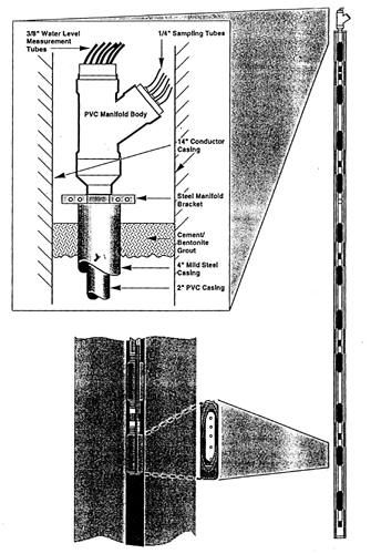
Steel conductor casings, 25 feet in length and 14 inches in diameter, were installed as part of each multilevel monitoring well. The top of the conductor casing was used as the vault for the Waterloo system's control manifold. However, we learned that if a steel conductor casing is to be used as the vault, the casing should be no less than 16 inches in diameter for ease in system installation and operation (see Figure 2).
Figure 2. Schematic of a Multilevel Monitoring Well with a Waterloo Multilevel Groundwater Monitoring System
Design of Gravel Pack and Seals
Prior to installing the well casing for each multilevel well, a caliper log was performed of the well bore. A caliper log is an absolute necessity for placing the gravel packs and seals. During gravel pack and seal placement, our driller frequently referred to the caliper log to estimate the volume of material to add. When placing the bentonite/sand seal it is critical that the driller does not overshoot the seal's position. Both gravel pack and bentonite/sand seal must be placed slowly, with frequent tagging of the top of the seal or gravel pack to determine its depth.
Gravel packs were 20 feet in length and were constructed such that they extended approximately 5 feet above and below each 10-foot screen section. A fine Monterey sand was used for the gravel pack material. Placement of a bentonite/sand seal on top of each gravel pack interval did not occur until the gravel pack was consolidated by gentle swabbing inside the adjacent well screen. Bentonite/sand seals were placed between the gravel packs to prevent the vertical migration of groundwater in the well's annular space. The sand that is added to the bentonite adds competence to the seal so that it can be easily tagged and support the weight of an overlying gravel pack. Bentonite/sand seals consisted of an approximate 50/50 mix. Bentonite/sand seals were tremied into the annular space by a positive displacement method of pumping. The displaced bentonite drilling fluid that was used to drill the well bore was used to convey the dry mixture into the annular space. Our driller informed us that using water to convey the dry mix into the well would cause the mix to immediately hydrate and clog the tremie pipe. Another important consideration in specifying the bentonite/sand mix i~ the size gradation of the mix. The bentonite should be fine such as Baroid Benseal®. Avoid the use of chips or pellets. The sand should also be fine such as Lonestar Industries #2/12. Two of the eight multilevel monitoring wells constructed for this project used Lonestar Industries "Coarse Aquarium" sand for the bentonite/sand mix and the result was frequent clogging of the tremie pipe due to the coarseness of the sand. The change to the finer sand significantly reduced the time for seal placement.
CONSIDERATIONS FOR MULTILEVEL WELL DEVELOPMENT
Once constructed, development of the multilevel wells consisted of swabbing and pumping each individual screen section. Development pumping of an individual screen involved the use of a submersible pump isolated between two inflated packers. Upon completion of development, a video log was made of the interior of each well. The purpose of the video log was to verify the depth of each 10-foot screen and the condition of the well. Recall that once the Waterloo system is installed, there will not be an opportunity to assess the condition of the well with a video log.
During the video log, it is important to document (within 0.5 foot) the bottom of the well and the top and bottom of each screen for comparison with the well construction log. Video logs taken of each of the eight multilevel wells constructed showed that even after development was complete, the bottom screen was still caked with mud. Consider that with mud rotary drilled wells, the heavy mud tends to settle in the bottom of the well and swabbing, bailing, and pumping may be ineffective on a mud-caked screen. To remove the mud, the bottom screen in each multilevel monitoring well was redeveloped with a jetting tool. Another consideration is to provide a contingency for any additional hours of well development that might be needed. If a factory representative from Solinst Canada Ltd. is to be on site for the installation of the Waterloo systems, immediately notify them of the delay so they can adjust their arrival schedule.
CONSIDERATIONS FOR INSTALLATION OF WATERLOO SYSTEMS
The Waterloo system consists of a string of 2-inch PVC easing and a series of self-inflating packers positioned above and below a sampling port for each well screen (see Figure 2). For each individual well screen, inside the easing and packers there is a 1/2-inch water level sounding tube (or transducer cable), a 1/4-inch nitrogen tube, and a 114-inch water sample tube. Groundwater samples are obtained using nitrogen gas and a portable control unit that drives the double valve pumps located near the intake ports. Water levels are measured using an electric sounder with a small diameter cable that is inserted down the sounding tube or with the permanently installed pressure transducers and portable readout box.
Installation of the Waterloo systems in the eight multilevel monitoring wells at Norton AFB required 10 days: eight days for the installation of the systems and two days for
equipment adjustments and modifications. Each Waterloo system installation was conducted using four-person teams, with two persons at the well head guiding the assembly down the well and two persons laying out the system components on top of the plastic sheeting. The team leader should be at the well head and should be responsible for keeping track of the order of installation of the system components. In our ease, the Solinst factory representative was the second team member at the well head assisting EARTH TECH's team leader.
It is recommended that the two other persons laying out the system components have good stamina and patient temperament because they will have to "thread" each PVC casing component and packer over small inner water level and sample tubes. While one person stands at the end of the plastic sheeting holding the inner tubes taut, the other person walks along the length of the plastic, threading each system component through the tubing until reaching the wellhead. In other words, for a 700-foot multilevel well with six sampling ports, it is estimated that the person threading the easing components will have to walk over 5 miles. With this in mind, it may be advisable to alternate field team members if several systems are to be installed over a short period of time. Walkie-talkies may be helpful in this regard.
Inventory all Waterloo system components prior to setup at a well site. It is advisable to order additional packers and casing components should some become damaged during shipment or installation. EARTH TECH ordered one additional packer for quality assurance purposes. That packer was inserted in a 2-foot section of blank casing and immersed in water. The quality of the seal created by the expansion material in the packer could then be verified. Waterloo system components are factory clcaned and scaled in plastic. For the Norton APB multilevel wells, great care was taken to keep the Waterloo system components as clean as possible. PVC casing and packers were not removed from their protective plastic covers until just before being threaded over the inner tubing.
Prior to installing the Waterloo systems, the team leader should develop an installation schedule that shows the depth of each system component to be installed in the well. It is during this process that the exact position of the packers is determined above and below each 10-foot screen section. Ideally, a packer should be placed against blank well casing rather than the well screen. If using Roscoe Moss mild steel/stainless steel dielectric couplings, there is approximately 1 foot of stainless steel blank easing before the flush threaded connection with the well screen section. Thus, using the video log to pinpoint the depth of the joints between the well screen and dielectric connectors, the packers can be adjusted plus or minus 0.5 foot without being placed in the wire-wound screen or not exposing the mild steel casing between the two packers.
Other helpful hints when installing the Waterloo systems are as follows:
- Make sure the connection between the sample tube and sample port is tight but not so tight as to crack the polyethylene tubing.
- Plan on enough water to fill the Waterloo system to the surface, or at least 40 inches above the static water level. Use tap water, not deionized water.
- At the top of the well, at the manifold cap, be careful not to over tighten the connection for the nitrogen gas tubes. If the threads become stripped, the result will be a loss in nitrogen and a reduction in water from the discharge.
- Slit the small plastic caps that go on the ends of the water discharge tubes. If the water level rises in the well, pressure in these tubes will build, causing the end caps to pop off.
- For accurate water level measurements, make sure the water level measurement tubes in the Waterloo system are taut when connected to the manifold cap. Also use the utmost caution not to get the tubes mixed up. If this happens you will not be able to determine which sampling port each tube is associated with.
CONSIDERATIONS FOR LONG TERM MONITORING
Monthly sampling of the eight multilevel monitoring wells at Norton AFB has been ongoing since May 1994. A complete sampling (for VOCs) from all 39 sampling ports takes only four 8 hour days. During each sampling round, approximately four 250-cubic foot cylinders of 99.99 percent pure nitrogen gas is usually expended and only 50 gallons of water is purged from all 39 sample ports.
Since the initial sampling of these wells, only minor difficulties have surfaced, with each being either repaired or resolved in the field. One of the few operational problems was the buildup of moisture inside the well vaults. Moisture has only been a problem in the wells with transducers, which caused the magnet in the transducer control cap to rust. The result was erroneous water level readings from the pressure transducers. The magnets in each of the wells with transducers have since been replaced. Because it can be difficult to completely eliminate condensation in the well vault, plan on taking time for periodic replacement of parts that might rust. Solinst Canada Ltd. has since redesigned this device to prevent such problems.
The only other operational difficulty that has been encountered during water sampling is the tendency, every so often, for the ball in the double valve pumps to become stuck. However, it is fairly simple to dislodge the ball by reversing the flow of nitrogen down the water sample tube instead of through the nitrogen tube. Solinst Canada Ltd. has a special fitting for this purpose and it usually only takes a few minutes to get a double valve pump working properly again.
CONCLUSIONS
The eight multilevel monitoring wells, each with Waterloo Groundwater Monitoring Systems, have been successful in characterizing the vertical and lateral extent of a plume of TCE that is migrating southwest of Norton AFB. The success of these wells is associated with the careful thought that went into many of the factors, mentioned above, affecting their location, design, and construction. With regard to the Waterloo systems, their success was in part recognizing their suitability to this particular application. The considerations for Waterloo system installation and long term monitoring mentioned above reflect only minor drawbacks from a nearly perfect scenario regarding their installation and operation;
REFERENCES
-
The Earth Technology Corporation, Norton Air Force Base Central Base Area Operable Unit Remedial Investigation Report Supplement Groundwater Characterization Off-Base Trichioroethylene Plume Investigation Preliminary Data Report (Phase I Report), prepared for Norton Air Force Base and the Air Force Center for Environmental Excellence, August 21, 1992.
-
The Earth Technology Corporation, Final Norton Air Force Base Central Base Operable Unit Remedial Investigation Report Supplement. Off-Base Trichioroethylene Plume Investigation Phase II Report, prepared for Norton Air Force Base and the Air Force Center for Environmental Excellence, January 14, 1994.
ACKNOWLEDGMENTS
The work described here was performed under United States Air Force Contract No. F33615-9O-D-4007 Delivery Order 0016. Data that are presented are with the permission of the Air Force Center for Environmental Excellence, Norton AFB, and Solinst Canada Ltd.
The author expresses kind thanks to those who reviewed the manuscript at EARTH TECH's Colton Office, namely Sandy Cuttino and Alain Sharp. Special thanks are given to Don Campbell of EARTH TECH's San Antonio Office, who supervised the installation of the Waterloo systems and provided input for this paper.