Tip:
It is recommended to take a manual water level measurement before installing a Water Level Temperature Sensor, shortly after installation, periodically during your monitoring interval, and at the end of your measurement period. Use these measurements to verify WLTS readings, and for data adjustments later on. Ensure you take manual readings as close in time as possible to a scheduled WLTS reading.
Note:
The WLTS can withstand over-pressurization of 2 times the intended range, e.g. a Model M10 can accommodate a fluctuation of 20 meters or 60 feet and still record pressure. However, over-range accuracy is not guaranteed.
Before Deployment, make sure you do the following:
- Program your WLTS, using the WLTS Utility, with the correct settings
- Locate the zero point of the pressure sensor, which is indicated by the machined line around the body of the Sensor
- Determine deployment depth to ensure the WLTS does not touch the bottom of a tank, well, etc. (avoid submergence in sediment)
- Determine the minimum and maximum expected water levels, as the WLTS must remain submerged for the entire monitoring period, without over-ranging the pressure sensor.
- Use a Solinst Model 101 or 102 Water Level Meter to take a manual depth to water measurement that will be used to verify WLTS readings.
Note:
The length of the Communication/Vented Cable should not be assumed as the deployment depth, as there may be some slack in the cable.

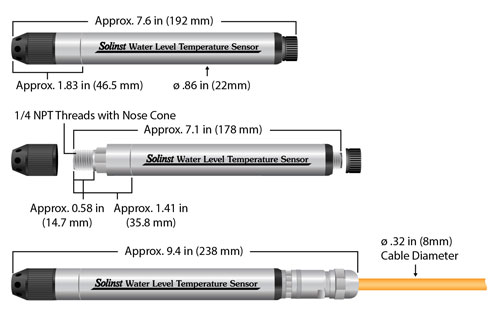
Solinst 301 Water Level Temperature Sensor Dimensions

Measurement Principles
Absolute Level:
When submerged, absolute pressure sensors measure total pressure – the pressure of air plus water column above their zero point. The actual pressure of just water above the sensor is obtained by subtracting barometric pressure from the total pressure.
Vented (Gauged) Level:
When submerged, vented pressure sensors detect both water and barometric pressure. However, a vent tube to surface allows barometric effects on the pressure sensor to be eliminated. Therefore, they provide readings of the actual pressure of just water above the pressure sensor zero point.
Deployment
- The WLTS is designed to be conveniently installed in a number of applications, as long as proper precautions and recommendations are followed.
- The nose cone of the Sensor can be removed to make use of the 1/4" NPTM threaded connection.
- Do not drop the WLTS into the water, carefully lower it into place. Avoid installing in areas where "water hammer" or hydraulic jump" (very sudden, large increases in pressure) may occur.
- Be careful not to nick or bend the Vented Cable during installation (use a maximum 1" (25 mm) bend radius as a precaution). Do not kink or nick the vent tube at surface.
After Deployment, make sure you do the following:
- Take a manual depth to water measurement after the WLTS has stabilized (approximately 10 minutes).
- Take another manual depth to water measurement just before removing the WLTS.
Once the Water Level Temperature Sensor has been installed and powered up, you can start configuring it.
Note:
See the 301 Water Level Temperature Sensor User Guide for your specific communication protocol (MODBUS, SDI-12) for full definitions of the available commands.


