
Model 405 Sampling Guidelines for Water Flute Systems

Water Flute Sampling Guidelines – Contents
1. Water Level in the Liner
The liner water level should be approximately 10 ft above the highest formation water level to provide a good seal of the liner in the hole (5 ft minimum excess head). The formation water level can be measured via the “pump tube” for each port. The water level inside the liner should be tagged in the 1/2 x 5/8″ tube labelled “TAG” adjacent to the sampling tubes. If the water level inside the liner is measured in the liner, outside the Tag Tube, lower the weighted tag line very slowly to avoid damage to the liner. Water can be added to the liner by simply pouring water into the liner or through the TAG tube, whichever is easier. Do not fill the liner more than 10 ft above the highest formation water level. The water level in the liner should be checked prior to each sampling episode.
2. Water Flow
The water flow into the pumping system is shown in Figure 2-1. Water flows from the formation through the spacer pore space, through the port tube, through the first check valve, and fills the “pump tube”. The “sample tube” is also filled at the same time. The water level rises in the pump tube to the water table for that port.
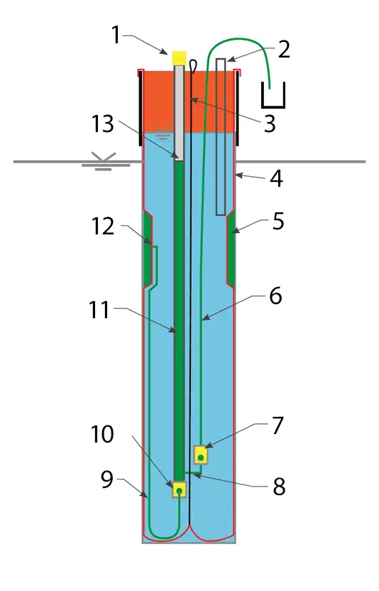
Figure 2-1 Water Flow in the Pumping System
Water Flow Components in the Pumping System
- Pump Quick Connect
- TAG Tube
- Tether Support of Tubing Bundle
- Sealing Liner
- Spacer Defining Monitoring Interval
- Sample Tube
- Second Check Valve
- Bottom of the “U”
- Port to Pump Tube
- First Check Valve
- Pump Tube
- Port Behind Spacer Through Liner
- Formation Head in Pump
3. Setting up the Gas Pressure Source
The water is pumped with gas pressure. The Flute pump design is such that there is very low risk of aeration of the sample. The gas source is usually a nitrogen bottle with a regulator for setting the prescribed driving pressure. The arrangement of the Flute gas drive system is shown in Figure 3-1. The regulator is set to the proper gas pressure defined later.
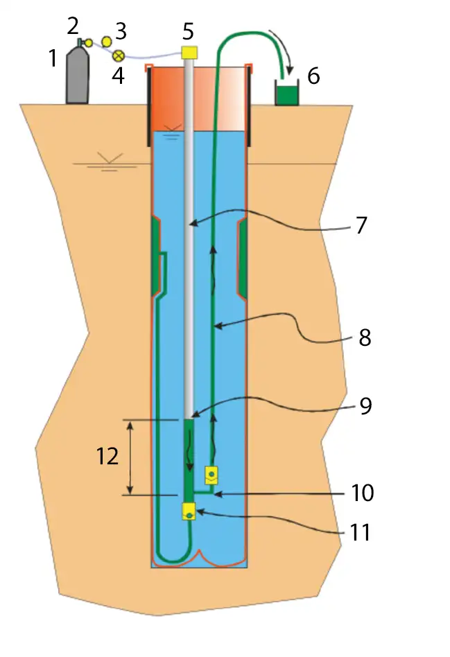
Figure 3-1 Water Flute Pumping Procedure
Flute Gas Drive System Arrangement
- Gas Bottle
- Regulator
- Gauge
- 3 Way Valve
- Quick Connect
- Sample Container
- Pump Tube
- Sample Tube
- Gas/Water Interface at End of Sample Stroke
- Bottom of the “U”
- First Check Valve (Closed)
- Buffer Against Aeration
The regulator is first attached to the top fitting on the gas bottle (a special nitrogen regulator fitting connects to a nitrogen bottle). Tighten the nut securely. Turn the pressure regulator handle anti-clockwise until it moves freely (the no pressure position). Rotate the main valve on the regulator (nearer the bottle) clockwise to fully closed. Open the valve on the bottle (anti-clockwise). The main bottle pressure gauge on the regulator will rise to the bottle pressure. Close the regulator valve (clockwise) until the pressure starts to rise on the pressure gauge on the Flute pump driver (three way valve closed with no flow out of the quick connect). Adjust the regulator to the desired pressure for purging, provided by Flute. Connect the quick connect to the top fitting of the pump tube (see Figure 3-1). Open the three way valve to drive the water out of the pump.
4. Purging
Water is pumped from the tubing by applying the gas pressure to the pump tube (Figures 2-1 and 3-1). The water is driven down in the pump tube and up through the second check valve to the surface via the sample tube. The purge stroke (approximately 1 gal. of water) is complete when gas is expelled from the sample tube following the water flow. The pressure in the system must then be vented to allow the pump tube to refill. The recharge flow from the port tube consists of the port tube water, the water in the pore space of the spacer, and water from the medium. Because of the relatively large volume in the pump tube, most of the recharge is from the medium.
Purging the pump tube a second time will remove any of the water that has resided in the spacer and port tube volume. That is highly recommended, since the water resident in the tubing and spacer is probably not typical of the formation water. If the refill has been prompt, the second purge water volume will be similar to the first stroke. Two more purge strokes, for a total of four purge strokes, are recommended to remove water that may have been in long contact with the liner or spacer.
5. Sampling
The sampling flow is best driven using a “recommended sampling pressure” which is less than that needed to drive gas through the bottom of the pump tube. The pressure recommended is that which will drive the water to near, but not out of, the bottom of the large tube. That recommended pressure is calculated in the spreadsheet provided with each system.
The first flow of the sampling cycle sweeps along droplets of water left in the tubing from the purge cycle. That residual water is depleted of volatile components. Tests have shown that the first tube volume of the sample flow should be discarded as depleted in volatiles (the “discard volume” is also calculated in the spreadsheet). Thereafter, the samples can be collected from the sample tube outflow. The volume to be discarded is shown in the spreadsheet as “discard volume”. The sample tube water flow rate will start fast, then slow, and finally stop. That occurs as the water column being driven approaches the applied pressure/head. The typical sampling pressure drives to within 25 ft of the bottom of the pump tube (the U). The large buffer zone remaining in the pump tube assures against aeration of the sample.
6. Measuring the Head in the System
The water level at each port can be manually measured by removing the plug from the top of the pump tube and lowering a slender (approximately 1/4″) electric water level meter until it contacts the water level in the pump tube.
The water level in the large tubes may not be the current water level. After sampling, if there is any leakage of the second check valve (sand in the tube, etc.) the water in the sample tube can backflow into the larger tube, adding to the water that fills the large tube during the recharge. Also, if the water level in the formation is dropping between head measurements, the water level in the pump tube will not follow the descent if the first check valve is a good seal. For these two reasons, and for the freezing concern below, it is best to finish the sampling stroke by raising the pressure to the “purge pressure” value to purge the pumping system of all water. Then upon refilling, the level is the current head for each port. If head measurements are made between sampling events, each port’s pumping system should first be purged one stroke to allow the tubing to refill to the current head value. Always replace the plugs in the top of the pump tubes when finished sampling.
If the water might freeze in the sampling tubing near the surface, purge the entire volume of water from each sampling line, after sampling, before leaving it. Use the recommended purge pressure to remove all water, not the sampling pressure. Each line should be blowing gas when the purge is complete.
7. Simultaneous Purge and Sampling of All Tubes
The Flute pumping system for each port is essentially identical in length, pump volume and elevation in the hole. This allows all ports to be purged and sampled simultaneously for a great saving in sampling time. The only difference for simultaneous sampling is that the pressure source must include a tube to each port fitting at the wellhead. Flute offers a manifold pump driver system at extra cost (the single port driver is provided with the Water Flute). The recommended purge and sample pressures are the same as used for single port sampling.
In some cases, the buoyancy of the sampling system is so great when emptied of water during the simultaneous purge that the tubing bundle can cause the liner to invert. The sampling volume spreadsheet provided with the liner notes whether the system can be purged simultaneously. This is only a problem for smaller hole diameters, many ports, and a small excess head in the liner. The new pump design allows simultaneous sampling in most situations.
8. Checklist
A short summary is provided as the following checklist:
- Check/restore the water level in the liner.
- Connect the gas driver source to the gas drive (pump) tube for the port.
- Set the regulator to the recommended purge pressure.
- Turn the three way valve and expel the tube water at the suggested purge pressure. Collect the purged water volume for verification of a good purge. Note the water flow time of the purge stroke (approximately 4 min.).
- Allow the tubing to refill. Repeat the purge. Collect the purge volume to assure the amount removed is at least the “port tube volume”.
- Purge a total of four times, more if desired.
- Allow the tubing to refill for the sample stroke.
- Reduce the driving pressure to the “sampling pressure”. Apply the pressure and collect the first flow to measure the discard volume. Discard that water. Collect the samples.
- Perform a final purge of the water out of the sampling lines by raising the driving pressure to the purge pressure value.
- When the sampling system has refilled, tag the water level, if desired, for the current water table. If a port system is refilling very slowly, tag it at a later time.
See the spreadsheet provided with each Water Flute for the recommended purge and sampling pressures. Those are the pressures that can also be used for a simultaneous purge of the several ports. The spreadsheet flags the condition where all ports should not be purged simultaneously. In most cases, several of the ports can be purged simultaneously.
Related Products
Enhanced Bioremediation
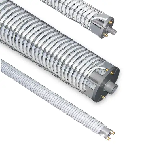
The Waterloo Emitter™is a simple, low-cost device designed for the bioremediation of contaminated groundwater. It enables oxygen or other amendments to diffuse through silicone or LDPE tubing in a controlled, uniform manner. Ideal for aerobic bioremediation of MTBE and BTEX, with minimal maintenance required.
3/8" Diameter Flexible Pneumatic Pump
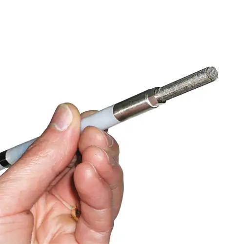
The Micro Double Valve Pump has a remarkably small and flexible design. At 3/8" (10 mm) diameter it is small enough to sample groundwater from channels of a CMT System.
Rugged Peristaltic Pump
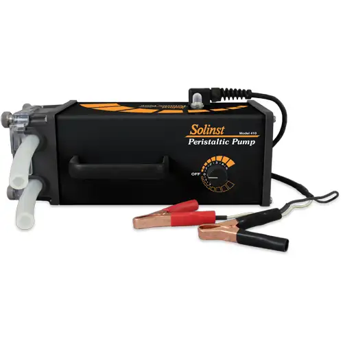
Compact, lightweight, and water-resistant, the Solinst Peristaltic Pump is designed for field use. One easy-access control allows various speeds and reversible flow. Ideal for shallow water and vapour sampling.
Tag Line - Rugged, Simple, Convenient
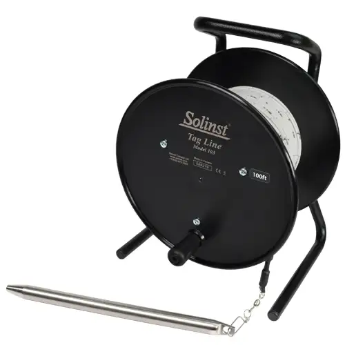
The Tag Line uses a weight attached to laser-marked cable, mounted on a sturdy reel. Convenient for measuring depths during monitoring well construction.


