
How Deep Must a Flute Blank Liner be Installed?

Purpose
This paper describes the rationale for installation of blank liners to less than full hole depth for an effective seal. The time required to install a blank liner depends very much upon the transmissivity distribution in the borehole. The time to effectively seal most holes is less than two hours and the liner may not be near the bottom of the hole when a sufficient seal of the hole has been obtained.
Background
A Solinst Flute Blank Liner is relatively easy to install and takes very little ancillary equipment. An installation procedure is available on a DVD for those who wish to install their own liners and to remove them as needed. The blank liner is installed by the process called eversion (the opposite of inversion) and as the liner propagates down the hole, it displaces the water from the borehole. The displacement is into all of the available flow paths into the formation. As the liner descends, it seals off the flow paths from the top down, and as each flow path is sealed by the liner, the remaining transmissivity of the borehole is less. Therefore, the liner initial velocity down the hole is relatively high and dependent upon the total transmissivity of the hole and the excess head in the liner. As the liner descends, the transmissivity is decreasing and therefore the liner installation rate is decreasing. Eventually, the liner descent rate will either be so slow as to not allow any further installation to be done in a practical time period, or the liner reaches the end of the hole. In many cases, the liner does not reach the bottom of the hole.
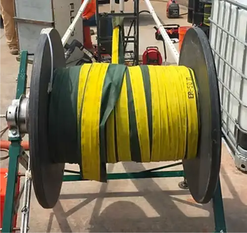
Solinst Flute Blank Liner on Shipping Reel
The Practical Limit of Liner Installation
If the liner descent seals the lowest flow path in the borehole and the transmissivity of the remaining borehole is zero, the liner velocity goes to zero, and there is obviously no need to install any further into the borehole.
In reality, after the last significant flow path is sealed, the liner velocity drops to a very low, but not zero, velocity. The liner velocity is a measurement of the flow rate out of the hole below the liner. The flow rate, Q, is just the hole cross section times the velocity. The transmissivity of the remainder of the hole is T = dz C =Q ln(r/r0)/(2 π dH), where dz is the open hole length, C is the conductivity, Q is the flow rate determined from the liner velocity and hole cross section, r/r0 of the order of 1000, and dH is the driving excess head in the liner. The fact that the liner descent is a flow rate measurement from which T can be calculated is used in another Solinst Flute procedure to measure the entire transmissivity distribution of the borehole. (However, that measurement is only done with special equipment and Solinst Flute personnel).
How long does it take to get to a liner velocity so low that the rest of the hole has an insignificant conductivity? Or, how low is that sufficiently low velocity? The answer depends somewhat upon the situation and the time period that the liner is to seal the hole. However, some reassuring facts are these:
- The liner is pushing the water into the formation. That is a necessary part of the liner installation. Driving, at most, one hole volume of water into the formation is normally not a concern if the hole is well sealed thereafter. If the liner does not descend to the bottom of the hole, the water displaced into the formation is less than one hole volume.
- The liner is driven by the excess head in the liner. If the liner is tied to an anchor point preventing its further descent, there is essentially not driving head forcing the water into the formation and the water beneath the liner may remain in the hole.
- The liner velocity at the deepest point in the hole is a measure of the remaining transmissivity in the open borehole. Therefore, regardless of the length of hole still open, the transmissivity of the borehole beneath the liner is measured by the liner velocity.
- Given a sufficiently low transmissivity, there is no concern about significant flow out of the hole after the liner is tied off and there is no longer an over-pressure of the remaining open borehole. What is that sufficiently low transmissivity?
- Given an open hole beneath the liner, it must have a vertical gradient in the formation over that interval to cause any flow out of the hole, and the worst case would be that half the remaining transmissivity is at a higher head than the other half of the remaining transmissivity. This relates to the fact that if there is no inflow, there can be no outflow; and the inflow is equal to the outflow in a closed volume.
Unfortunately, the head distribution in the borehole is not known, so the gradient in the remaining open hole is not known. Therefore any judgment of a sufficiently low velocity must depend on the general understanding of the local hydrologic situation. However, there are some reasonably safe assumptions:
- If all of the remaining transmissivity in the hole below the liner is in one zone of uniform vertical head, there is no source zone to drive water out of that remaining zone. Therefore, the hole is sufficiently sealed forever.
- If the flow out of the unsealed portion of the hole was no more than the remainder of the open hole volume, that would be no different than driving the liner to the bottom of the hole. The time during which that much flow may occur is no concern. That time is calculated hereafter.
- After that flow time, the subsequent flow would be a concern if the inflow zone was contaminated and the outflow zone was uncontaminated.
- The flow rate out of the hole below the liner is directly related to the ratio of the natural driving head difference in that open portion of hole to the driving head during the liner installation. We know the flow rate during the installation. The outflow can be estimated with any assumed head difference in the unsealed interval.
- Unless the unsealed interval straddles two aquitards, the head difference in the interval below the liner is likely to be relatively small.
The above generalizations allow one to estimate the rate of flow out of the interval below the liner.
While performing a typical hydraulic conductivity profiling of a borehole, we usually stop the measurement when the liner velocity drops to less than 0.001 ft/sec, or 0.06 ft/min (a higher value for smaller holes). That means the tether/liner is advancing into the hole at twice that velocity or 1.5″/min. For a nominal 5 inch hole, that is about 0.06 gal/min with our typical driving head of 15-20 ft. This corresponds to a remaining transmissivity in the hole of ~ 0.02 cm2/s. If 20 ft of the borehole is open below the liner at that time, we can estimate the time it would take to empty that volume of water in the hole below the liner into the formation if we assume a head difference in the hole below the liner. With an assumed 0.5 ft head difference in the 20 ft interval, it would take 18 days for that 20 ft of hole volume to be displaced into the formation. That result is for the worst case in which half the transmissivity was inflow and half was outflow from the hole. If the open hole is longer for the same final velocity, the time is proportionately longer.
If the head difference is larger or the velocity is higher, the time is proportionately shorter. In most cases the maximum flow out of the hole is much less than 1% of the flow with the hole open. The main reason is that the liner seals the more transmissive zones and typically drastically reduces the vertical head difference in the remaining open hole. The installation cutoff for profiling is generally well below the cutoff for a temporary blank liner installation.
The Recommended Installation Time
Our conductivity profiling experience shows that most holes are well sealed in less than ~2 hrs of blank liner installation. If there is a fast flowing zone near the bottom of the hole, it can be done in much less time. If the hole has a very low total transmissivity and most of that is in the bottom portion of the hole, it may be practical to install for longer than 2 hrs. The recommended installation tether velocity will leave a transmissive zone below the liner of ~0.2 cm2/s. The suggested time to end the installation is when the tether/liner is moving into the hole with a velocity less than or equal to:
Minimum tether/liner velocity = 20 inches/min. x (dH/15′) x (3″/r)2
Where dH is the driving head used in feet (typically the depth to the water table or less than 20 ft), r is the radius of the hole. For a 6″ diam. hole and 15 ft of driving head, the tether velocity cutoff would be 20 inches/minute. For a driving head of 15 ft, this often means about a 2 hour installation or less. This leaves a remaining transmissivity below the liner of 0.2 cm2/s.
The velocity is best measured with about a 5 lb tension on the tether. This cutoff is independent of the hole length. If the driving head is only 5 ft in the 6″ hole, the cutoff would be reduced to ~7″/min. It is obviously faster to use a driving head greater than 5 ft. Fortunately, the cutoff velocity may be obtained very abruptly when the liner passes the last major flow path.
If a lower transmissivity is required for some special reason (e.g., 0.1 vs. 0.2 cm2/s), the minimum velocity can be reduced proportionately. That will prolong the installation and also the removal.
If the liner is to be left in place for only a few weeks, it is not necessary to seal so much of the hole as for longer times in place. The tether velocity can be determined by marking the tether twenty inches from the top of the casing and measuring the time for the mark to reach the casing. If about 1 minute, it is time to consider tying off the tether/liner. It is often useful to install the liner to at least half its length so that only the tether remains outside the hole. But that is a convenience, not a necessity.
A significant practical consideration is that the time required to remove the liner is similar to the time that it takes to install the liner. If one reaches a very low velocity and then fills the liner without tying it to an anchor at the wellhead to prevent its descent, the liner will continue to propagate down the hole until the excess head in the liner is exhausted. That has the two disadvantages of not having a sufficient excess head in the entire liner to provide a good seal, and it may require a very long time to remove the liner by inversion. It is strongly recommended that one does not allow the liner to propagate until the excess head has decayed without refilling the liner.
The liner installation and removal should be done with a good understanding of the procedure for both. That
procedure is available from Solinst Flute at [email protected], or by calling +1 (505)-852-0128.
Related Products
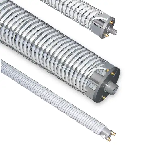
Enhanced Bioremediation
The Waterloo Emitter™is a simple, low cost device designed for the bioremediation of contaminated groundwater. It enables oxygen or other amendments to diffuse through silicone or LDPE tubing in a controlled, uniform manner. Ideal for aerobic bioremediation of MTBE and BTEX, with minimal maintenance required.
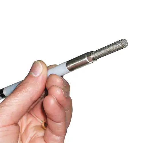
3/8" Diameter Flexible Pneumatic Pump
The Micro Double Valve Pump has a remarkably small and flexible design. At 3/8" (10 mm) diameter it is small enough to sample groundwater from channels of a CMT System.
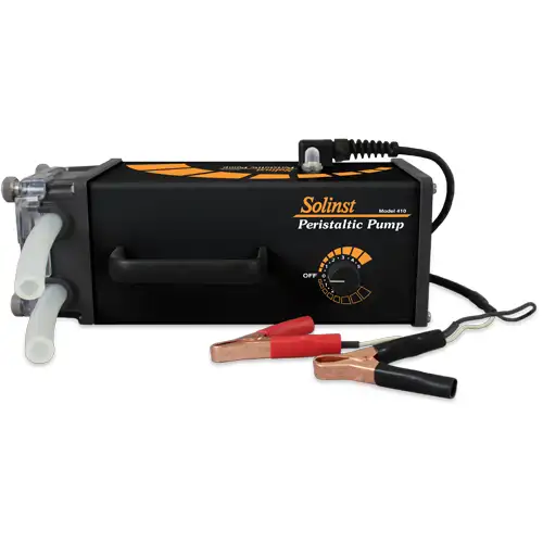
Rugged Peristaltic Pump
Compact, lightweight, and water-resistant, the Solinst Peristaltic Pump is designed for field use. One easy-access control allows various speeds and reversible flow. Ideal for shallow water and vapor sampling.
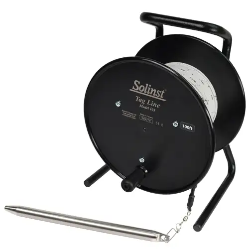
Tag Line - Rugged, Simple, Convenient
The Tag Line uses a weight attached to laser marked cable, mounted on a sturdy reel. Convenient for measuring depths during monitoring well construction.


