Peristaltic Pump Head Replacement Model 410 Mk4/Mk3
Note:
See section below for instructions to install the pump head on an Mk3 Peristaltic Pump.
Tools and Materials Needed
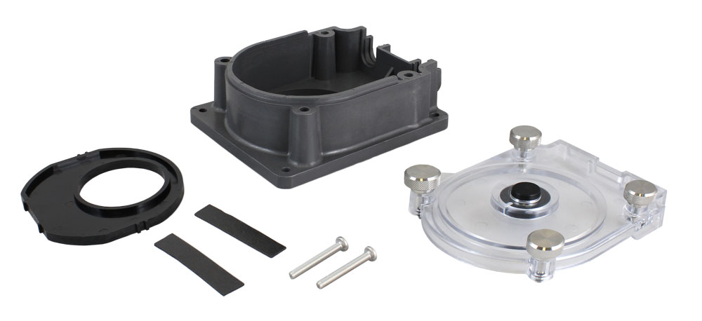
- Replacement Mk4 410 Peristaltic Pump Head Assembly (#113949)
- 9/64″ (3.60 mm) Allen Key
- 11/32″ (8.70 mm) Nut Driver
- Phillips Screwdriver

Solinst Mk4 Peristaltic Pump (#112981)
Instructions
Note:
The motor brace and foam tape are not required when replacing the pump head on a Mk4 Peristaltic Pump.

- Disconnect the pump from the power supply. By hand, loosen the four thumbscrews on the pump head. Remove the pump head cover.

- Manually rotate the head roller while pulling gently on the tubing to remove it from the pump head.

- Use the 9/64″ (3.60 mm) Allen key and 11/32″ (8.70 mm) nut driver to unscrew and remove the socket screw, nut, and washer from the head roller. Remove the head roller from the motor shaft.
- Unscrew the two Phillips screws from inside the pump head.
- Use the nut driver to remove the four tapping screws from the pump head. Remove the old pump head from the pump housing.
- Place the new pump head over the motor shaft and attach it to the pump housing using the two Phillips screws and four tapping screws.
- Rotate the shaft of the motor so the screw hole in the shaft is vertically facing. Slide the head roller onto the motor shaft and secure it using the screw, washer, and nut. Make sure the head roller turns freely and is not touching the pump head.
- Position the tubing around the impeller in a “U” shape with equal lengths. Turn the impeller to the 6 and 12 o’clock position and push the right hand tubing into the tubing pathway, holding near the bottom. Rotate the impeller clockwise until tubing is in place. Push the left half of the tubing into place and rotate the impeller.
Note:
To use 3/8″ tubing with the new pump head, you will require Tubing Adaptor Kit #113913 (see Peristaltic Pump Operating Instructions). Tubing adaptor kits used with the original Mk1, Mk2 or Mk3 pump head will not work with the Mk4 pump head.

- Position the pump head cover and screw it firmly in place by hand. Thumbscrews should be finger tight. Do not use a wrench or over-tighten.
Tools and Materials Needed
- Replacement Mk4 410 Peristaltic Pump Head Assembly (#113949)
- 9/64″ (3.60 mm) Allen Key
- 11/32″ (8.70 mm) Nut Driver
- Phillips Screwdriver

Solinst Mk3 Peristaltic Pump (#108592)
Instructions

- Disconnect the Peristaltic Pump from the power supply. By hand, loosen the four thumbscrews on the pump head. Remove the pump head cover.

- Remove the tubing clamps if necessary and manually rotate the head roller while pulling gently on the tubing to remove it from the pump head.

- Use the 9/64″ (3.60 mm) Allen key and 11/32″ (8.70 mm) nut driver to unscrew and remove the socket screw, nut, and washer from the head roller. Remove the head roller from the motor shaft.
- Unscrew the four Phillips screws from inside the pump head and remove it from the end plate.
- Undo the four screws from the end plate and remove the end plate from the pump housing.

- Disconnect the black and red wires from the motor terminals.
- Unscrew the motor adaptor from the end plate. You will not need this end plate with the new pump head.
- Unscrew the adaptor and remove it from the motor. You will not need the adaptor with the new pump head.
- Slide the motor brace onto the motor until it seats against the two terminals. Secure in place using the foam tape.
- Fasten the new pump motor to the pump head using the two Phillips screws.

- Reconnect the red and black wires to the motor terminals.
- Align the tabs on the motor brace with the grooves in the pump housing and insert the motor into the pump housing. Secure the new pump head to the pump housing using the four screws.
- Rotate the shaft of the motor so the screw hole in the shaft is vertically facing.
- Slide the head roller onto the motor shaft and secure it using the screw, washer, and nut. Make sure the head roller turns freely and is not touching the pump head.
- Position the tubing around the impeller in a “U” shape with equal lengths. Turn the impeller to the 6 and 12 o’clock position and push the right hand tubing into the tubing pathway, holding near the bottom. Rotate the impeller clockwise until tubing is in place. Push the left half of the tubing into place and rotate the impeller.
Note:
To use 3/8″ tubing with the new pump head, you will require Tubing Adaptor Kit #113913 (see Peristaltic Pump Operating Instructions). Tubing adaptor kits used with the original Mk3 pump head will not work with the Mk4 pump head.

- Position the pump head cover and screw it firmly in place by hand. Thumbscrews should be finger tight. Do not use a wrench or over-tighten.
Related Products

415 12V Submersible Pump
The Solinst 12V Submersible Pump provides an efficient means of purging and obtaining groundwater samples from 2" OD monitoring wells. The compact pump can sample from depths of 36.5 m (120 ft) below ground surface, and is easy to adjust the flow rates up to 13.5 L/min (3.6 US gpm) in shallower applications.

800M Mini Packer
The 800M Mini Packer is 1 ft in length and is designed to fit in nominal 2" OD monitoring wells to temporarily isolate discrete zones for groundwater monitoring and sampling applications – available as a single and straddle packer setup.

Make Your Life Easier In The Field
Consider making your life easier in the field by ordering one of our convenient Field Tables. We have two models available, Well-mount and Stand-alone, to keep your equipment organized and provide a clean, sturdy surface to hold your field tools.
Well-mount Field Table - 115209
Stand-alone Field Table - 115312