Preparation
Depth Discrete Groundwater Monitoring
Reduce Costs and Field Time
Note:
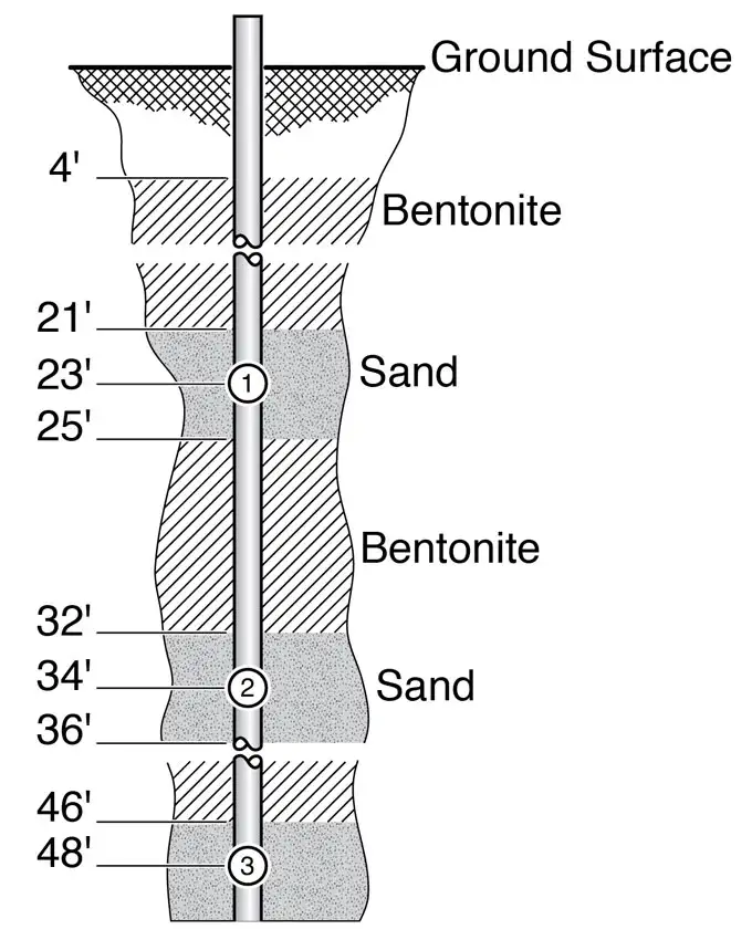
Allow 2 ft or more of sand above and below each port.
Before making any ports in the CMT tubing, make a sketch of the desired well design. Show the depths of the desired monitoring zones and centralizers (if used) in feet or meters below ground surface. Also, indicate the depths of the desired lifts of sand and bentonite, as shown graphically on Figure 1.

Figure 1 – 3 Channel CMT Multilevel System Schematic of Sampling Port Setup
Note:
If you are installing sand or bentonite cartridges, please also read ‘Cartridge Installation’ Section.
This will come in handy when you are measuring the depths of the backfill materials while you are building the well. If you are building a CMT well where alternating layers of sand and bentonite backfill are added from the surface, try to allow for two feet or more of sand above and below the monitoring ports to ensure that the bentonite does not cover the monitoring ports. Allow sufficient wellhead access when you install the protective cover over the well.
Note:
Avoid using “single lifts” of grout greater than 50 ft. in the unsaturated zone.
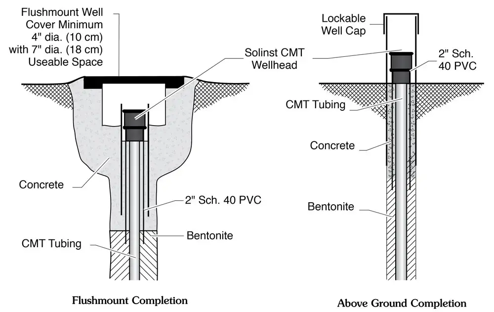
Use a large well cover (greater than 4″ diameter is recommended) to allow plenty of room to access the wellhead. A diagram showing suggested dimensions of the wellhead and protective cover is shown in Figure 2 for flushmount and above ground completions.

Figure 2 Showing 403N Narrow CMT Multilevel System
Flushmount and Above Ground Well Completions
