Note:
When sampling for volatiles, because the drive gas never comes in contact with the inside of the Bladder or Sample Line, you do not have to worry about aerating the sample. The slow compression of the Bladder also minimizes turbulence, and allows for a steady low-flow discharge.
Operating Steps
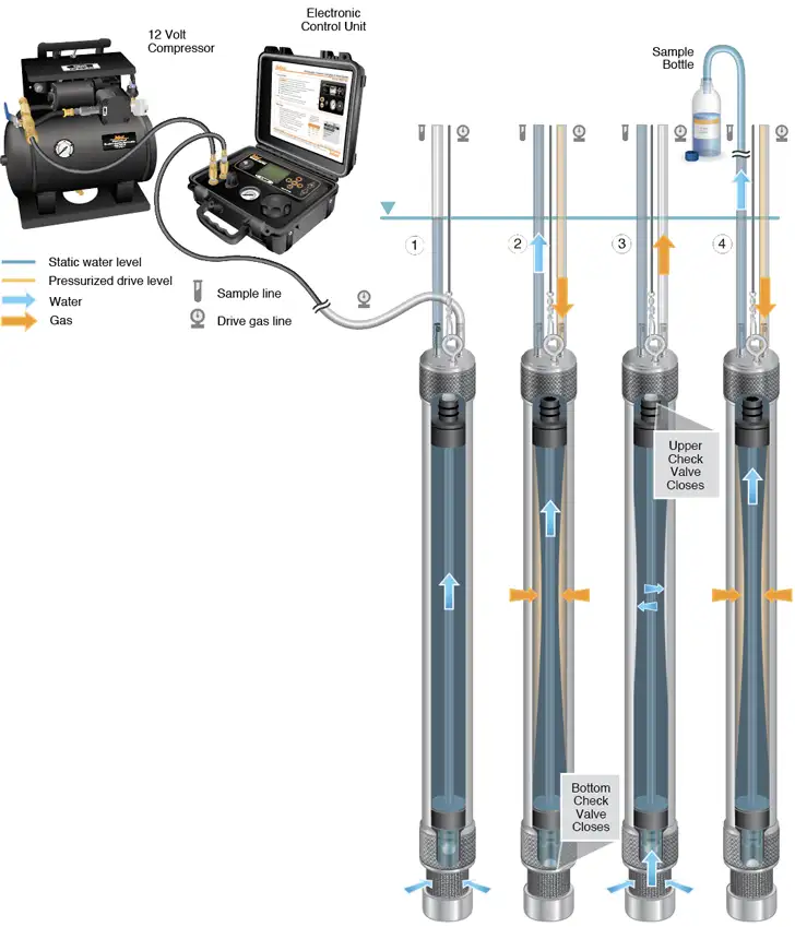
- The Bladder Pump is submerged in the well. Hydrostatic pressure forces water through the Pump filter intake and fills the Bladder and the Sample Line to static water level.
- Use an Electronic Control Unit to apply pressure from a compressed air or Nitrogen source to the Drive Line, and into the Pump space around the Bladder.
The actual pressure needed is calculated based on Bladder Pump intake depth below ground surface in feet, divided by 2.3, with 20 psi added for line loss (e.g. Pump intake 100 ft below ground surface ÷ 2.3 + 20 psi = minimum 63 psi needed.)
The pressure causes the Bladder to slowly compress, while the Bottom Check Valve closes, forcing water from the Bladder into the Sample Line. The drive gas never comes in contact with the sample water.
- The Control Unit automatically switches to vent mode, allowing the discharge of drive gas at the wellhead. When the Drive Line has been vented to atmosphere, water pushes the Bottom Check Valve up, and the Bladder refills due to hydrostatic pressure.
Water is held in the Sample Line during the vent cycle, by the Upper Check Valve closing.
- Pressure is re-applied to the Drive Line, compressing the Bladder, and raising the level in the Sample Line closer to the surface.
After repeated cycles of pressure and vent, water in the Sample Line is discharged at surface in a gentle pulsating flow.


