Single Point Packer: Installation & Inflation
Model 800 Pneumatic Packers are inflated with air via 1/4" (6.4 mm) O.D. tubing extending from the packer to the surface. A manual hand pump with a gauge may be used to inflate the packer. Please read through these instructions fully before proceeding.
Note:
Figures A and B (found overleaf) illustrate centralizer installation for both Single Point and Straddle Packers. For packer specifications, borehole sizes and required inflation pressures, please refer to the charts below.
- Cut an appropriate length of 1/4" (6.4 mm) O.D. inflation tubing to extend from the packer to the surface. This tubing must extend to the surface with enough slack to allow ease of inflation.
- Push the top end of the inflation tubing into the push fitting on the inflation valve (to release tubing push down on both sides of the fitting and pull tubing out).
- Connect the other end of the inflation tubing to the packer. Push the tubing onto the stainless steel barb fitting. Check the connection by pulling firmly on the tubing. It should not pull off of the fitting.
Note:
Use an awl to open the very tip of the tubing, or heat the tubing to help push it completely over all the barbs.
- The system is now complete and should be installed by connecting the appropriate riser pipe and lowering the system into the well. Hang the riser pipe such that the packer is suspended at the appropriate depth.
- If a riser pipe is not used, then a safety cable should be attached to the eyebolt on the packer to allow securing at surface. The Solinst Tag Line can be used for this purpose. (See Model 103 Data Sheet)
Note:
All Model 800 Packers are designed for short term applications. However, if longer continuous usage is necessary, weekly monitoring of target inflation pressure and packer seal will be required.
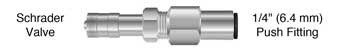
Inflation Valve
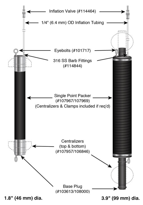
Standard Single Point Packer Setup with Inflation Lines

800 Packer Specifications (Single Point and Straddle Packers)
| Packer | 1.8" O.D. (46 mm) | 3.9" O.D. (99 mm) |
|---|---|---|
| Well Size | 1.9 - 2.4" (48 - 61 mm) | 4.0 - 4.4" (102 - 112 mm) |
| Inflation Pressure | 20 - 30 psi, 140 - 205 kPa | 20 psi, 140 kPa |
With Centralizers (trim to fit) |
||
| Well Size | 2.5 - 3.5" (63 - 89 mm) | 4.5 - 5.0" (114 - 127 mm) |
| Inflation Pressure | 35 - 40 psi, 240 - 275 kPa | 25 - 30 psi, 170 - 205 kPa |
|
Notes:
|
||
| Specifications | ||
|---|---|---|
| Borehole Size | 1.9 - 2.4" (48 - 61 mm) | 4.0 - 4.4" (102 - 112 mm) |
| - with centralizers (trim to fit) | 2.5 - 3.5" (63 - 89 mm) | 4.5 - 5.0" (114 - 127 mm) |
| Packer Size OD | 1.8" (46 mm) | 3.9" (99 mm) |
| Access ID | 1/2" (12.7 mm) | 1" (25.4 mm) |
| Gland Length | 23" (584 mm) | 30" (762 mm) |
| Overall Length | 29" (737 mm) | 36" (914.4 mm) |
| -with centralizers | 29" (737 mm) | 44" (1117.6 mm) |
| Pipe Fittings | 1/2" NPT - Female | 1" NPT - Male |
| -with centralizers | 1/2" NPT - Female | 1" NPT - Female |

