Tools and Materials Needed
- 464 Panel Mount Gauge 1/8" NPTM (Spare) (#111806)
- 3/32" Allen Key
- Flat Screwdriver
- 14 mm Wrench
- PTFE Tape or equivalent
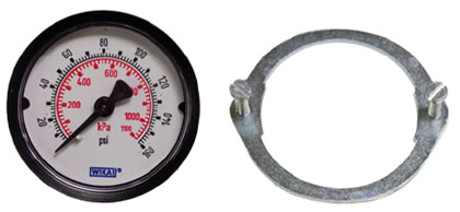
464 Panel Mount Gauge 1/8" NPTM (Spare) (#111806)
Instructions
- Turn the Control Unit off and remove the batteries.
- Use the 3/32" Allen key to undo the four hex screws on the sides of the Control Unit.
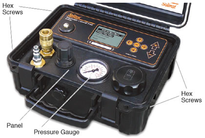
- Remove the panel from the Control Unit and flip it over to access the Pressure Gauge.
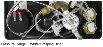
- Push down on the white “grasping ring” on the elbow fitting and pull to remove the tubing from the elbow on the Pressure Gauge. Note the orientation of the elbow; you will reattach it to the new Pressure Gauge in a similar position.
Note:
You may wish to remove other tubes in order to more easily access the Pressure Gauge. Ensure they are properly reconnected after the new Pressure Gauge is installed.
- Use the flat screwdriver to loosen the two screws from the metal ring holding the Pressure Gauge in place.
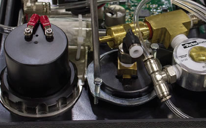
- Twist to unlock the metal ring from the Pressure Gauge, then remove the ring and the Pressure Gauge from the panel.
- Use the 14 mm wrench to remove the elbow fitting from the old Pressure Gauge.
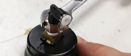
- Wrap PTFE tape (or equivalent) around the threads on the new Pressure Gauge and screw the elbow fitting onto the threads. Note the orientation of the elbow when tightening; you should match its original position.
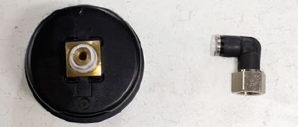
- Slide the new metal ring with the screws into place on the back of the panel.
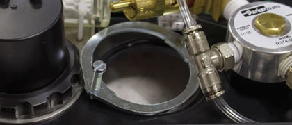
- From the front of the panel, insert the new Pressure Gauge through the opening. Ensure it is oriented properly.
- Line up, and twist the metal ring onto the new Pressure Gauge to lock it into place. Tighten the two screws and ensure the Pressure Gauge is still positioned correctly on the front of the panel.
Note:
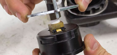
The photo below shows how the metal ring lines up with the slot in the side of the Pressure Gauge. The ring slides into the slot, and is twisted to lock in place.
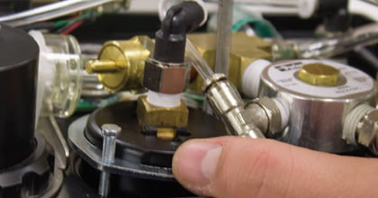
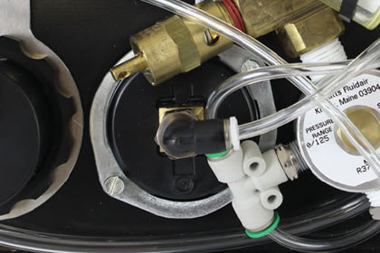
- Ensure the elbow fitting is oriented correctly (see photo) and push the tubing into the fitting. (Reconnect any other tubes that you may have previously disconnected.)
- Place the panel in the Control Unit case and re-install the four hex screws.
- Reinstall the batteries. Test the Control Unit using compressed air to ensure proper connections were made when replacing the Pressure Gauge.


