Operating Principles
|
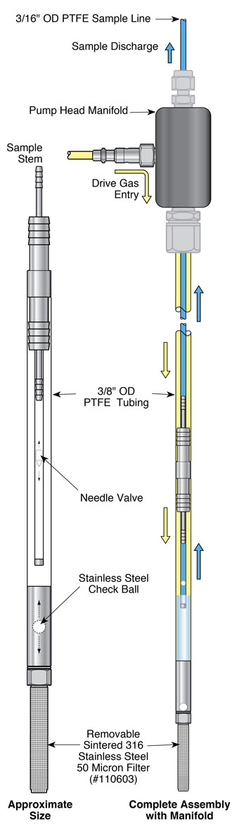
When the Solinst Micro Double Valve Pump (DVP) is placed in a well or borehole, water rises inside the pump and up the concentric tubes to static level. A Control Unit is used to supply compressed gas or air to the pump on the drive cycle. The gas pushes down on the water column contained in the outer, 3/8" dia. tubing (drive line), closing the check valve at the base of the pump. This forces the water up the inner 3/16" dia. sample line tubing. A vent cycle, during which the gas is released, allows water to refill the pump and drive line (outer tubing). The top check valve prevents water in the sample line from falling back into the pump body. This drive and vent cycle is repeated manually or automatically as set by the timers on the control unit. The cycle may be regulated for purging or sampling.
Note: The pump has been cleaned before leaving Solinst, however, if you wish to decontaminate your pump before use, follow the decontamination procedure here.
Purging/Sampling Setup
Note: Always support the 408M Pump by holding onto the 3/8" OD tubing. Never support the pump by the Pump Head Manifold only.
Taking a Sample with the Micro Double Valve Pump
|
|
Note:
Please refer to the 464 Electronic Control Unit User Guide for proper setup and operation using a compressed gas source. 464 Electronic Control Unit User Guide
3. Adjust the control unit “Pressure Regulator” to the appropriate value [(pump intake depth below grade in feet x 0.43) +10 psi].
4. Adjust the Drive and Vent times on the Model 464 Electronic Control Unit to adjust the sampling flow rate to the desired amount.
5. During the Drive period on the Control Unit, the sample line will produce your water sample. During the Vent period on the Control Unit, the Drive Line is filling again under hydrostatic pressure.
6. For Double Valve Pump Optimization, select the desired flow rate from the
pre-set screens. Use the Flow Regulator to adjust flow to your desired rate. If a higher flow is required, slowly increase the Drive time to increase the flow rate. If air is expelled, decrease the Drive time. To further optimize the flow rate, increase or decrease the Vent time until the highest flow rate is achieved.
7. Once optimum flow rates have been achieved, make note of the pressure, flow rate and timer settings for subsequent sampling dates. For example, with an 85 ft. - 408M assembly and a static water level at 60 ft. With a pump pressure of [(85 ft. x 0.43) + 10psi] = 50psi., a suitable drive of 11 sec. and vent of 9 sec., will produce a flow rate of about 150mL/min.
Note:
Unthread the filter between sampling events and store separately.