Strain Relief Replacement Model 410 Mk3
Tools and Materials Needed
- Replacement Strain Relief (Spare) for the Peristaltic Pump (Set of 5) (#112239)
- 5/16″ Wrench
- Small Flat Screwdriver
- 15/16″ Wrench
- Scissors or Small Utility Knife
- Wire Cutters and Strippers
- 3″ 1/4″ Inner Melt Heat Shrink (#104115)
- 1.5″ 3/8″ Inner Melt Heat Shrink (#100878)
- Soldering Iron and Wire
- Heat Gun
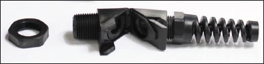
Replacement Strain Relief
Instructions
- Disconnect the pump from the power supply.
- Using the 5/16″ wrench, remove the four screws from the end plate (opposite end from pump head).
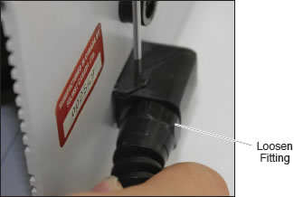
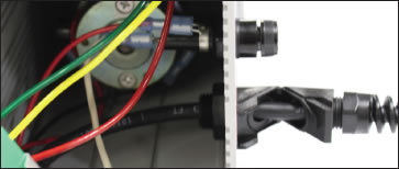
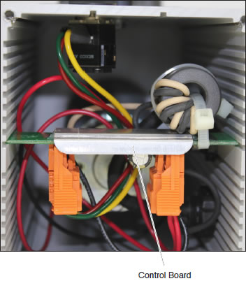
- Loosen the fitting on the strain relief. Use the small flat screwdriver to pry open the strain relief on the power cable on the outside of the pump housing. See photo below.
- Carefully slide the control board out of the enclosure.
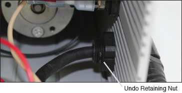
- Use the 15/16″ Wrench to undo the retaining nut from the strain relief on the inside of the pump housing.
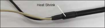
- Use the Scissors or small utility knife to carefully remove the heat shrink from the power cable. You will replace this later, below.
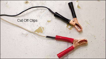
- Cut off the battery clips right at the heat shrink.
- From the inside of the pump housing, pull the wires of the power cable all the way through and out of the old strain relief.
- Position the new strain relief on the pump housing using the retaining nut. Feed the power cable through the strain relief until about 6″ of the jacketed part of the cable is in the pump housing.
- Strip the ends of the wires, where the battery clips were removed, by 5/8″.
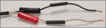
- Slide the 1.5” piece of 3/8” inner melt heat shrink over the two wires and out of the way, to replace what was removed in step 6.
- Pull off the red and black grips from the battery clips (use the grips that are opposite from the ones where the wires were previously connected). Slide the red grip onto the white wire, and the black grip onto the black wire. Push them out of the way.
- Cut off two 1.5″ long pieces of the 1/4″ inner melt heat shrink, and slide one onto each wire. Push the heat shrink out of the way.
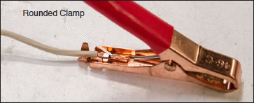
- Slide the white wire into position in the red clip handle. Ensure that stripped wire is showing on either side of the rounded clamp. See the photo below for proper positioning.
- Use the end of the pliers or a screwdriver to apply pressure to the rounded clamp until it is securely clamped to the stripped wire.
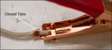
- Use the pliers to close the two tabs on the clip handle around the white wire.
- Repeat steps 13, 14, and 15, using the black wire and black clip.
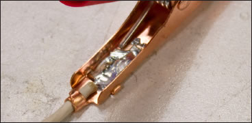
- Solder the white wire to the red clip at the rounded clamp. Ensure there is a good pool of solder, and that solder is visible in the opening on the opposite side of the clip handle.
- Repeat step 17 with the black clip.
- Slid the pieces of heat shrink up to the clips, and position as shown in the photo. Apply heat using the heat gun.
- Apply heat to the 3/8” heat shrink, further up the power cable.
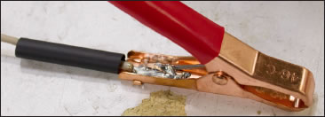
- Slid the grips over the heat shrink and onto the handles of the clips.
- Slide the control board into the pump enclosure in the slots, plugs facing down.
- Carefully push all wires into the housing. Pull the excess power cable in the pump housing through the new strain relief, then lock the strain relief.
- Screw the end plate back on the pump.
Related Products

415 12V Submersible Pump
The Solinst 12V Submersible Pump provides an efficient means of purging and obtaining groundwater samples from 2" OD monitoring wells. The compact pump can sample from depths of 36.5 m (120 ft) below ground surface, and is easy to adjust the flow rates up to 13.5 L/min (3.6 US gpm) in shallower applications.

800M Mini Packer
The 800M Mini Packer is 1 ft in length and is designed to fit in nominal 2" OD monitoring wells to temporarily isolate discrete zones for groundwater monitoring and sampling applications – available as a single and straddle packer setup.

Make Your Life Easier In The Field
Consider making your life easier in the field by ordering one of our convenient Field Tables. We have two models available, Well-mount and Stand-alone, to keep your equipment organized and provide a clean, sturdy surface to hold your field tools.
Well-mount Field Table - 115209
Stand-alone Field Table - 115312