Tools and Materials Needed
- 3/32" Allen Key
- Small Utility Knife
- 7/64" Allen Key
- 11/16" Wrench
- 14 mm Wrench
- 1/2" Wrench
- 7/16" Wrench
- Cotton swab
- Distilled water
- Any suitable plastic adhesive (e.g. silicone)
Instructions
Note:
These Instructions are for Solinst Model 464 250 psi Electronic Pump Control Units sold between September 2013 and January 2016.
- Turn the Control Unit off and remove the batteries.
- Use the 3/32" Allen key to undo the four hex screws on the sides of the Electronic Pump Control Unit.
- Remove the panel from the Control Unit and flip it over to access the Solenoid Valve Assembly.
- Push down on the fittings to remove the three black tubes from the Shuttle Valve Assembly, and the two clear tubes from the Solenoid Valve Assembly (photo shows black tubes removed).
- Use the 7/64" Allen Key to remove the three screws from the bracket holding the Shuttle Valve Assembly, and carefully slide the Shuttle Valve Assembly out from the bracket.
- Use a small utility knife to break any adhesive holding the Solenoid Connector to the Circuit Board. Unplug the Solenoid Connector from the Circuit Board.
- Use the appropriate wrenches to remove the two fittings (shown on Page 2) from the Shuttle Valve Assembly. Twist to remove the Solenoid Valve Assembly from the Shuttle Valve Assembly.
- Unscrew the brass fitting from the Solenoid Valve Assembly, and remove the magnetic plunger.
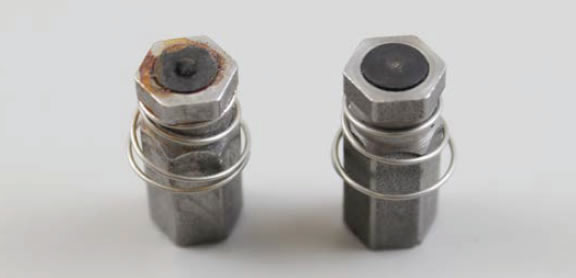
- Inspect the small rubber circular pad on the end of the plunger. If this pad is damaged, dented, etc. the Solenoid will not seal properly, therefore you may need a new Solenoid Valve Assembly. (Contact Solinst). See photo below comparing a damaged pad to a pad in good condition.
- To clean the Assembly, use a cotton swab and distilled water to clear any debris and dirt from inside the brass fitting, around the o-ring, steel fitting and from the magnetic plunger.
- Ensure the o-ring is properly seated inside the brass fitting. Insert the magnetic plunger back into the Solenoid Valve Assembly, and screw the brass fitting back onto the Assembly.
- Screw the Solenoid Valve Assembly into the Shuttle Valve Assembly. Screw the two fittings back into the Shuttle Valve Assembly (see top left photo for proper connections).
- Plug the Solenoid Connector back into the Circuit Board, and apply a small amount of adhesive to the outside of the Connector to help secure it to the Circuit Board.
- Slide the Shuttle Valve Assembly back into place under the bracket and secure it using the three screws.
- Push the three black tubes back into the fittings on the Shuttle Valve Assembly. Use the photo on Page 1 to ensure correct connections.
- Push the clear tubes into the fittings on the Solenoid Valve Assembly. Use the photo on Page 1 to ensure correct connections.
- Place the panel in the Control Unit case and reinstall the four hex screws.
- Reinstall the batteries. Test the Control Unit to ensure proper connections were made and the Solenoid is now functioning.


Note:
The photo above shows the tubing fittings and Shuttle Valve Assembly fitting removed from the Solenoid Valve Assembly, you do not need to remove these.