Introduction
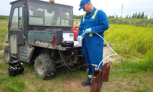
Retrieving a groundwater sample using a Bladder Pump or Double Valve Pump, requires answers to two main questions-–how much pressure and volume of drive gas is required? And how are proper drive and vent times determined?
Pneumatic Pumping Pressure
Determining the amount of applied pressure (in psi) to retrieve a sample is simple. 1 psi of pressure can raise a 2.3 ft. column of water, which is about half of the column height of water in feet, expressed as psi. With both Bladder Pumps and Double Valve Pumps, add an extra 10 psi to allow for "line loss".
E.g. If the Bladder Pump's intake is at 100 ft. below ground surface, you will require approximately 50 psi of pressure to bring a sample to ground surface.
To be more precise:
Drive pressure
= (intake depth x 0.43) + 10 psi
= (100 x 0.43) + 10 psi
= (43) + 10 psi
= 53 psi
If you are taking a groundwater sample with a Double Valve Pump, then this calculation is made from ground level to static water level (as a minimum, but can be made from total pump depth to maximize purging rates). Therefore, if a Double Valve Pump is 100 ft. below ground surface, and static water level is at 50 ft., you can select a pressure of between 25 and 50 psi.
Drive pressure
= (depth to water x 0.43) + 10 psi
= (50 x 0.43) + 10 psi
= (22) + 10 psi
= 32 psi
Groundwater Sampler Drive Gas
The drive gas is usually air or nitrogen delivered through portable gas cylinders, or an air compressor. Portability to the site and pressure requirement for the application are the main deciding factors.
If your groundwater sampling protocol does not specify which drive gas to use, then consider these points:
Portability: Keep in mind that a larger volume air tank means a larger and heavier air compressor. A 3 to 5 CFM air supply is relatively portable. Single stage (125 psi) compressors are available through most rental outlets, while dual stage (300 psi) compressors are more expensive and harder to find.
Suitability: If the larger size air compressor is not suitable for your sampling needs, then you will need to choose a bottled gas supply, such as a nitrogen tank, to provide portability and sufficient pressure to lift water to ground surface. Generally, you should allow for 10 L of gas to push 1 L of water.
The selection of either compressed nitrogen or air is based on the potential for affecting groundwater sample quality.
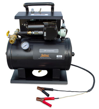
Solinst 12 Volt Oil Less Air Compressor
Solinst 12 Volt Compressor
When the Solinst 12 Volt Compressor is turned ON, the compressor motor will continue running until it reaches a maximum tank pressure of 150 psi. At this point, the compressor motor will turn off automatically. When the drive cycle on the Pump Controller is activated, the compressor tank supplies air through the drive line to the pump. The compressor motor will remain off until the tank pressure drops to 100 psi. At 100 psi, the compressor motor automatically switches on, and stays on until 150 psi pressure is produced in the air tank.
To ensure a long life with any air compressor, operate it so that the compressor motor is not always on, which can lead to overheating the motor. To help maximize the life of your Solinst 12 Volt Compressor, we suggest using a conservative 50% duty cycle and a maximum 100 ft. pumping application depth.
Two key specifications on the 12 Volt Compressor Operating Instructions are, the 2 US Gal (7.6 L) tank volume, and the auto-on at 100 psi (~200 ft.). If your Bladder Pump intake is 200 ft. below ground surface, after about three drive cycles the compressor motor will turn on, and stay on if the vent time was less than 3 times the drive time. A longer vent time would allow the air compressor to catch-up for deeper pumping applications.
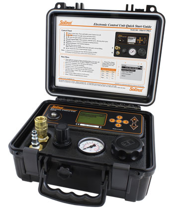
Solinst Model 464
Pneumatic Pump Controller
To use your Solinst 12 Volt Compressor for sampling applications deeper than 100 ft., consider shorter durations and good pumping conditions – high water column above the pump to provide good recharge, longer vent time for the air compressor to refill, and cool ambient air temperatures to help reduce heat on the compressor motor. As with any air compressor, avoid long-term overheating of your compressor motor.
Pump Controller - Setting the Timers
Turn the regulator on the Pump Controller to the calculated pressure needed to push water to ground surface. To help protect the Pump Controller from damage due to moisture, always position the Pump Controller physically higher than the sample discharge and wellhead. This helps prevents a syphoning effect, where the gravity back-flow of sample water can enter into the Pump Controller, and cause unnecessary damage.
407 Bladder Pump
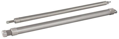
Solinst Model 407 Bladder Pumps
Drive Time:
- Submerge the sample discharge line into a clear container of water
- Push the Manual Control Valve on the Pump Controller
- Count the number of seconds until you stop seeing air bubbles in the container of water
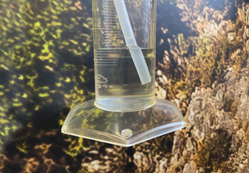
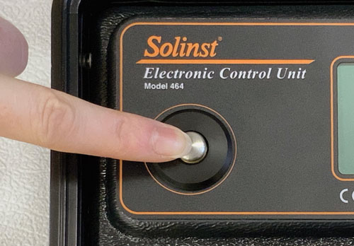
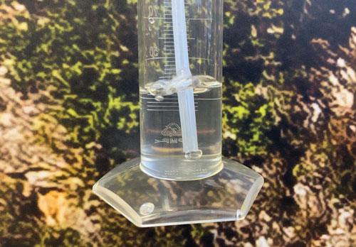
When the air bubbles stop, the bladder is fully compressed and that is the end of the drive time.
Vent Time:
When the intake of the Bladder Pump is shallower than 100 ft., set the vent time twice as long as the drive time. E.g. if it took 8 seconds of drive time to fully collapse the bladder, you should allow 16 seconds for the vent time to refill the bladder. When the Pump intake is deeper than 100 ft., the vent time will be closer to 3 to 4 times the drive time. Adjust the vent time as needed for deeper applications and to achieve an ideal flow rate for your sampling needs.
408 Double Valve Pump
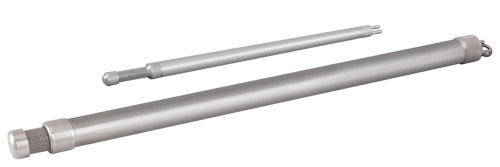
Solinst Model 408 Double Valve Pumps
Drive Time:
If the goal of your sampling method is to not allow the drive gas into the Double Valve Pump (DVP) itself, then you can determine that volume by evacuating the water in both the drive line to the pump, and the sample line from the pump.
- Place the sample discharge line into an empty collection container
- Push the Manual Control Valve on the Pump Controller
- Count the number of seconds until you stop seeing water discharge, and gas starts to be expelled from the tubing
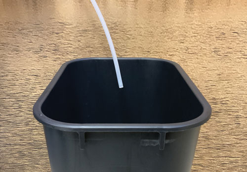

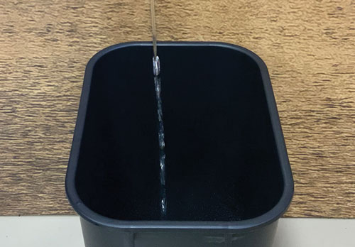
This time period is the maximum drive time to completely empty the DVP assembly. Now, set the drive time on the Pump Controller to a time about 40% of this evacuation time.
E.g. if it took 20 seconds to completely evacuate the drive and sample lines, set the drive time on the Pump Controller to 40% of 20 seconds (0.4 x 20 seconds = 8 seconds).
Why 40%? Generally, half of the total time was used to empty the drive line tube, and the other half of the time was used to empty the sample line. As a factor of safety, 40% of the total time should be sufficient to ensure that the drive gas stays above the DVP itself.
This calculation is based on the well recharge, being capable of 'keeping-up' with the sample discharge. If you start noticing drive gas within the sample discharge, shorten the drive time until the water sample is discharged without the presence of drive gas.
Vent Time:
Similar to the Bladder Pump, with a Double Valve Pump, start by setting the vent time twice as long as the drive time. E.g. if you calculated the drive time to be 8 seconds, you should allow 16 seconds for the well to recover (vent time).
Vent time increases with deeper submergence and slower well recharge. As depth to water increases, or well recovery slows, set the vent time closer to 3 to 4 times the drive time.
Note: In appropriate conditions, you can use a Solinst Water Level Meter or Water Level DrawDown Meter to time the static water recovery. This can also be used as your vent time.
Tip: What do you do when your pneumatic pump is properly connected, yet there is no sample discharge? A simple 'trick', is to submerge the sample discharge line into a clear container of water. During the drive cycle, you should see bubbles. An aggressive blast of air bubbles can mean that there is no water available, while a steady mild bubbling indicates that the pump is operating and the sample water is on the way up!


