Operating Steps
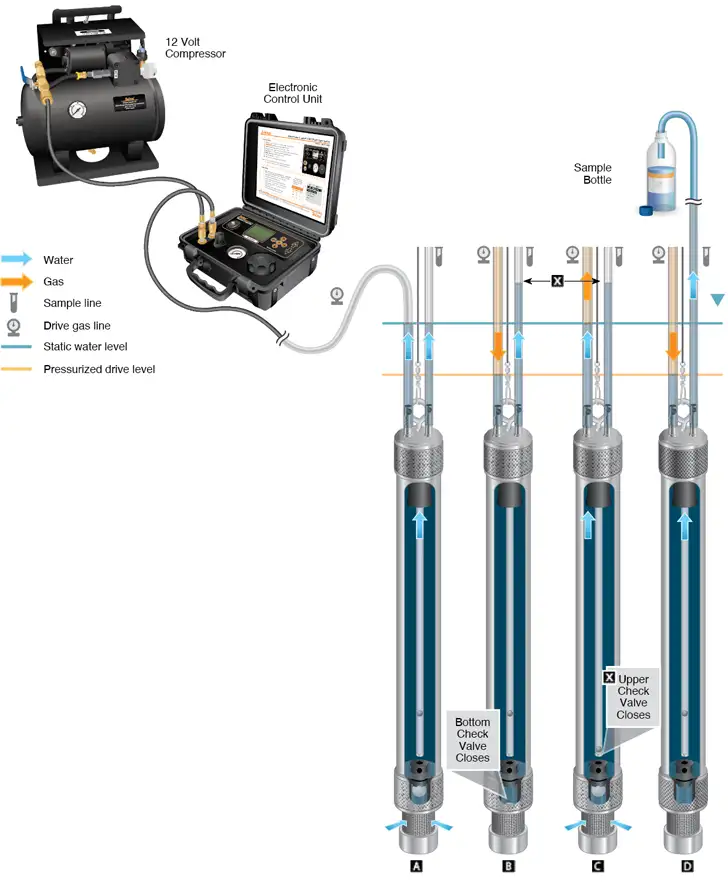
(See diagram below)
The Pump is submerged in the well. |
||
|
Hydrostatic pressure forces water to fill the pump body and both the Drive and Sample Lines to static water level. |
|
Use an Electronic Pneumatic Pump Control Unit to apply pressure from a compressed air or Nitrogen source to the Drive Line. The pressure should not be too high to allow air into the Pump Body. |
||
The actual pressure needed is calculated based on depth to static level in feet, multiplied by 0.43, with 10 psi added. (e.g. 50 ft to static x 0.43 psi/ft level + 10 psi = 31.5 psi needed.) |
||
|
Water in the Drive Line circulates through the Pump and up the Sample Line. The Bottom Check Valve closes to prevent water returning to the formation. |
|
|
The system is allowed to vent, and the level in the Drive Line tubing recovers to static level, as water flows in through the filter intake at the base of the Pump. |
|
|
The Upper Check Valve of the Double Valve Pump closes to prevent water from draining back down the Sample Line. The water level in the Sample Line remains constant and above the static water level. |
|
|
Pressure is re-applied to the Drive Line, circulating water from the line through the Pump, and raising the level in the Sample Line closer to the surface. |
|
|
After repeated cycles of pressure and vent, water in the Sample Line is expelled at surface in a gentle pulsating flow. |
|
Note:
For the collection of volatiles, the pressure applied must never be too high, nor too long in duration, to enable gas to enter the body of the Pump and aerate the sample. Always calculate pressure based on static level + 10 psi, increasing the pressure and/or the drive time only incrementally to improve performance.


