Double Valve Pump Operating Principles
When the Solinst Double Valve Pump (DVP) is placed in a well or borehole, water rises inside the pump and the twin tubes to static level. A Control Unit is used to deliver compressed gas to the pump. During the drive period the gas pushes down on the water column contained in the drive line tubing, closing the check valve at the base of the pump. This forces water up the sample line tubing.
A vent period, during which the gas is released, allows hydrostatic pressure to refill the pump and drive line with sample water. The top check valve prevents water in the sample line from falling back into the pump body. This pressurization and vent cycle is repeated manually or automatically as set by the timers on the Control Unit. The cycle may be regulated for purging or sampling.
Note:
- The maximum lift for stainless steel pumps is 500 ft. (150 m).
- DO NOT exceed an operating pressure of 250 psi.
- The 464 External Filter (#112832) is recommended if using a compressor to operate the Pump.
Pump Assembly
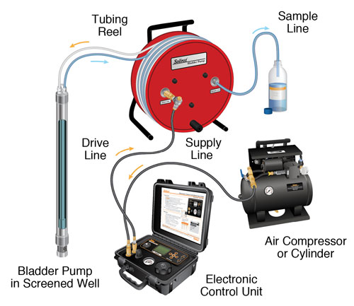
Portable: The Double Valve Pump is assembled by connecting it to skip-bonded, dual 1/4" OD tubing, mounted on a reel.
- To accommodate the 1/4" drive tubing, insert the 1/4" compression adaptor into the 3/8" drive line fitting on the Pump. The 3/8" fitting nut may have to be loosened first, then tightened after the 1/4" adaptor is inserted (see overleaf).
- Push the tubing inserts into the end of the tubing and into the drive and sample compression fittings of the DVP (the nut of the compression fittings may have to be loosened before inserting the tubing). Tighten the nut 1-1/4 turns past finger tight for proper seal (see overleaf).
- Lower the assembled DVP into the well, using a Kevlar cord or stainless steel safety line connected to the eye bolt on the pump. The Solinst Model 103 Tag Line can be used for this purpose.
- Connect the supply line with optional 464 External Filter from the compressed gas source to the Control Unit. The drive line connects from the Control Unit to the reel (drive and supply lines come with the Model 464 Control Unit).
- Attach a short (3 ft. or 1 m) length of 1/4" OD sample line to the sample connector on the reel.
Dedicated: The Double Valve Pump is assembled by connecting to a Dedicated Wellhead with 3/8" or 1/4" OD sample and drive line tubing.
- Cut the tubing to desired the lengths. See steps a) and b) above for tubing connection instructions to the Pump. The 1/4" compression adaptor for the drive line fitting on the Pump can be used if 1/4" drive line tubing is desired.
- Attach the sample and drive lines to the appropriate push fittings on the underside of the Wellhead (see diagram at right for use of push fittings and adaptors).
- Lower the DVP into the well, using a Kevlar cord or stainless steel safety line. Attach the safety line to the suspension hook on the underside of the Wellhead. Push the Wellhead firmly onto the riser casing.
- Attach a short (3 ft. or 1 m) length of 1/4" OD or 3/8" OD sample line to the sample connector on the Wellhead (see diagram at right for use of push fittings and adaptors).
- Connect the supply line with the optional 464 External Filter from the compressed gas supply to the Control Unit. The drive line connects from the Control Unit to the top of the Wellhead (drive and supply lines come with the Model 464 Control Unit).
For detailed pumping instructions, please see the Solinst Model 464 Control Unit Operating Instructions.
Note:
Tube fittings are based on use of 3/8" drive line and 1/4" sample line. A 3/8" to 1/4" adaptor is also supplied, if dual 1/4" tubing is preferred, or when using a portable reel.
Portable Sampling Setup
Dedicated Wellhead Setup (110227)
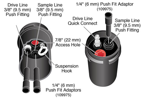
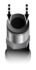
Wellheads come with three 1/4" push fit adaptors so that either 1/4" or 3/8" tubing can be used, as preferred.
To attach tubing just push into push fitting. To release tubing push down on both sides of the top ring and pull tubing out.
Optional Drive Line Adaptor (107117)
Drive Line "M Style" Quick Connect
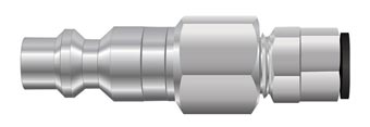
Drive Line 1/4" (6.4 mm) Push Fitting
When the Bladder Pump is deployed without a Wellhead or Tubing Reel, use a Drive Line Adaptor to allow the connection of the drive line quick connect fitting from the Control Unit to the drive line pump tubing.


