3.3.1 AquaVent Setup
Note:
See the Vented Dataloggers User Guide for detailed AquaVent installation Instructions.
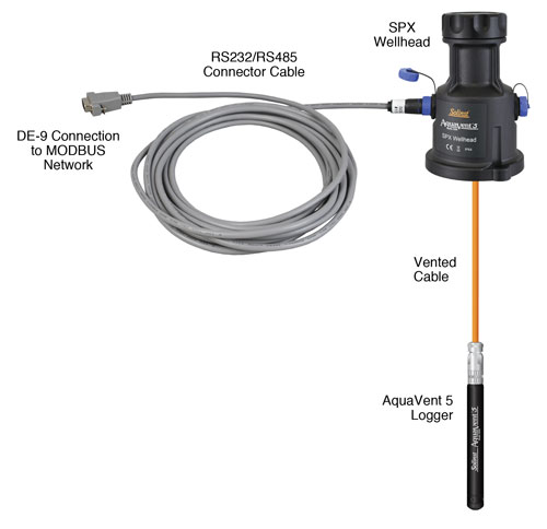
- Be sure that the AquaVent logger is properly connected to the SPX Wellhead using a Vented Cable. See the Vented Dataloggers User Guide for detailed AquaVent installation Instructions.
- Be sure the RS-232/RS-485 Connector Cable is connected to the 12-pin connection on the SPX Wellhead (Ensure you have unplugged the USB Connector Cable after using the AquaVent with Levelogger Software).
- Using the figures in Section 3.2, connect the RS-232 or RS-485 Connector Cable to the MODBUS equipment. Ensure you have correct pin-to-pin connection and external power supplied to the Wellhead.
- Turn on power to the SPX Wellhead. The SPX Wellhead LED should emit the following signals in order:
- Tricolour spin (3 cycles) to indicate a power-on event.
- Upon entering Field mode, a rapid 10 cycle alternation of Yellow/Green colour indicates that communication has been established with the AquaVent logger, and is running with the Baud rate and MODBUS device address prescribed by the AquaVent settings (which can only be changed by Solinst Levelogger PC Software).
- Upon entering Field mode, a rapid 10 cycle alternation of Yellow/Red colour indicates that the Wellhead has come online WITHOUT establishing communication with the AquaVent logger, and is running with the default Baud rate and MODBUS device address.
- The SPX Wellhead and the AquaVent logger are physically and properly hooked up to the MODBUS network.

Figure 3-9 Solinst AquaVent MODBUS Installation


