Data Compensations, such as Manual Data Adjustments and Parameter Adjustments can be performed automatically using the software Data Wizard, or manually, by exporting data to an external spreadsheet program.
6.1 Data Wizard
Open the Data Wizard tab. The first step is to select your Data Compensation Path. The LevelVent 5 and AquaVent 5 will only have the Advanced option available.
Note:
Multiple data files can be compensated at once.
The Advanced option allows you to perform Manual Data Adjustments and Parameter Adjustments.
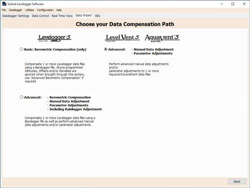
Figure 6-1 Data Wizard
Manual Data Adjustment allows you to enter a manual water level measurement or reference point as a field zero, which all water level readings can then be adjusted to. There is the option to convert readings to Depth to Water Level measurements (e.g. from the top of a well casing to water level), or Elevation of Water Level measurements (e.g. above sea level).
Note:
Manual Data Adjustment, and Parameter Adjustments are useful for correcting data files to make data consistent across a project.
Parameter Adjustments allow you to change data to different units of measurements, add an offset, or adjust density.
- Unit conversion allows you to convert level readings in a data file to different units (m, cm, ft, kPa, bar or psi), or temperature readings to ºC or ºF,
- Offset allows you to enter any value, positive or negative, which will be added to each reading in the selected data file to be offset by that amount. It is recommended to stay with the default zero value, unless a known offset has been determined (e.g. to correct for pressure sensor drift. See Solinst Technical Bulletin: Understanding Pressure Sensor Accuracy, Precision, Resolution & Drift.
- Density Adjustment corrects the range of the level channel in the data file based on a user input adjustment of fluid density. The range of the density adjustment is from 0.9 kg/L to 1.1 kg/L.
When you select Advanced compensation, the Data Compensation Options window will open.
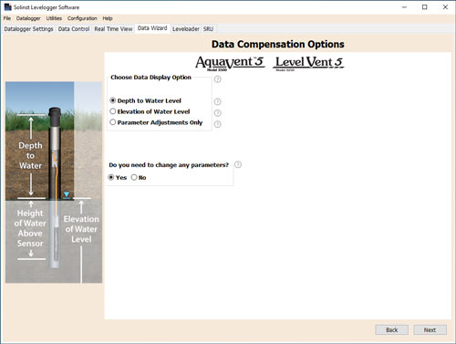
Figure 6-2 Data Compensation Options
First, you will select how you want your data displayed (Manual Data Adjustment):
- Depth to Water Level adjusts water level data to represent depth to water level readings (from the top of a well casing or other reference point) by entering a field zero, such as a manual depth to water level measurement. Adjustments can be made to one or more data files.
- Elevation of Water Level adjusts water level data to represent elevation of water level readings (above sea level or other reference point) by entering a measuring point elevation, and a field zero, such as a staff gauge measurement from that point. Adjustments can be made to one or more data files.
- Parameter Adjustments Only allows you to adjust one or more data files to different units, density, etc., while keeping the sensor diaphragm (zero point) as the reference point for datalogger.
Next, you will select Yes or No to performing any Parameter Adjustments on the data files (will not be active if you selected Parameter Adjustments Only).
Click Next, after you have selected all of your Data Compensation options.
In the next window, you will choose the data file(s) you would like to use in the compensation. Any files you have open in the Data Control tab will be listed.
Use the directory on the left of the window or click ![]() to open any other data files you would like to compensate. Ensure the files you want to compensate are highlighted in the list. Do this by clicking the file name. To de-select a file, click again. Select Next to continue.
to open any other data files you would like to compensate. Ensure the files you want to compensate are highlighted in the list. Do this by clicking the file name. To de-select a file, click again. Select Next to continue.
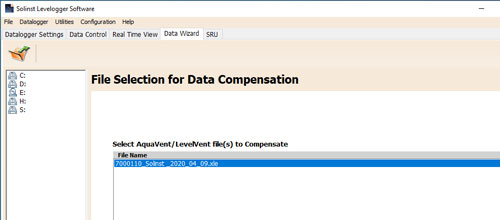
Figure 6-3 Selecting Files for Compensation
If you have selected yes to Parameter Adjustments, or selected the Parameter Adjustments Only option, in the next window you will enter these. If you did not select to change any parameters, this window will not be shown.
Note:
When adjusting Units, if you select apply to all, the same unit change will be applied to all of the files being compensated at that time.
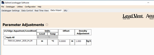
Figure 6-4 Parameter Adjustments
Next, for each selected data file, you will enter the Field Zero(s) you would like to use to manually adjust your water level data. (If you have selected Parameter Adjustments Only, this window will not be shown.)
For Depth to Water Level adjustments, enter a Field Zero (A). If the static water level is below your Field Zero measurement, the Field Zero is input as a positive value (e.g. a manual water level meter measurement taken from the top of a well casing. See Example 6.1). If the static water level is above your Field Zero, the Field Zero is input as a negative value (such as in a flowing artesian sealed wellhead condition).
The Time the Field Zero measurement was taken must replace an actual reading in the data file. This is selected from the drop-down menu showing all time stamps in the data file. Click 'Add' to apply the adjustment. If you need to change a Field Zero, click 'Update' after any edits.
Note:
The date and time of measurement of the Field Zero must be recorded to complete the adjustment. The Field Zero must replace an actual reading the data file. I.e. take a manual measurement immediately after starting the datalogger, and note that time.
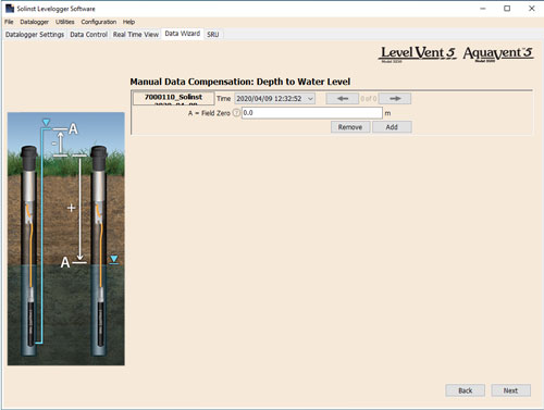
Figure 6-5 Manual Data Adjustment - Depth to Water Level
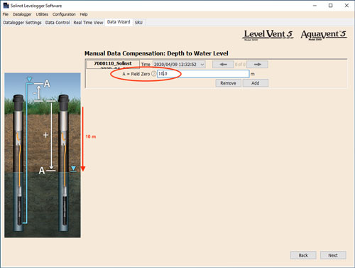
Example 6.1 Depth to Water Level Adjustment
When using a manual depth to water measurement taken from the top of a well casing as a Field Zero, enter it as a positive value (e.g. 10 m). In your adjusted data file, your readings will increase in value as the water level decreases. This is because the depth to static water level from the top of the well casing is increasing. The adjusted readings will decrease in value as the static water level rises.
| Original Data (height of water above sensor) |
8.75 m | 8.50 m | 8.75 m | 9.5 m | 9.75 m |
| Adjusted Data (depth to water) |
(A) 10.0 m | 10.25 m | 10.0 m | 9.25 m | 9.0 m |
For Elevation of Water Level adjustments, enter a Measuring Point Elevation (A) and a Field Zero (B) from that Measuring Point.
If the static water level is below your Measuring Point, the Field Zero is input as a positive value (e.g. if you are using a manual depth to water measurement as a Field Zero, from the top of a well casing as the Measuring Point).
If the static water level is above your Measuring Point, the Field Zero is input as a negative value (such as in a flowing artesian sealed wellhead condition). The Measuring Point elevation may also be entered as a negative value.
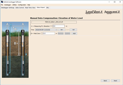
Figure 6-6 Manual Data Adjustment - Elevation of Water
The Time the Field Zero measurement was taken, must replace an actual reading in the data file, and is selected from the drop-down menu showing all time stamps in the data file. Click 'Add' to apply the adjustment. If you need to change a Field Zero, click 'Update' after any edits.
Note:
The date and time of measurement of the Field Zero must be recorded to complete the adjustment. The Field Zero must replace an actual reading the data file, i.e. take a manual measurement immediately after starting the datalogger, and note that time.
You can make multiple adjustments to one data file by selecting 'Add' again to enter another Field Zero. All readings after this Time, will be adjusted to this second measurement. You can add as many adjustments to one data file as you would like (as long as it doesn't exceed the total number of readings in that file).
Select Next to complete the compensation.
The compensated data will automatically be saved in a new *.xle file. The default file name will be the <original file name> with the word <compensated> added to the file name prefix. Alternatively, the user can rename the compensated file by saving it in the Data Control tab. Do not change or delete the file extension. All data files are saved to the default location:
<C:\Program Files\Solinst\Levelogger4_7\Data>.
Note:
All data files are saved to the default location: <C:\Program Files\Solinst\ Levelogger4_7\Data>. However, the default directory for saved files can be changed by clicking the Configuration menu at the top of the program window, selecting 'Application Settings' and inputting or navigating to a different folder destination.
The next window will show the results of the compensation. If the compensation was unsuccessful, there will be an explanation in the Reason column. You can still view the compensated file in the Data Control tab, by clicking 'Open' in the Action column. If the compensation is successful, select 'Open', to view the compensated data file in the Data Control tab.
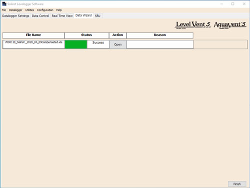
Figure 6-7 Data Compensation Results
If you have selected multiple files for compensation, there will also be the option to 'Open All' of the compensated files in the Data Control tab or 'Export All' of the compensated files at the same time. Options are to export as *.csv files or *.xml files.
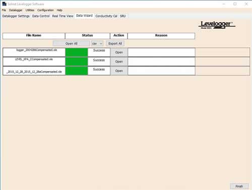
Figure 6-8 Data Compensation Results – Multiple Files
From the Data Control tab, you can view the data, save the compensated file with a new filename and/or export the data (see Section 5).
All the original datalogger settings and the channel information effective during data collection are shown on the top left of the window. The bottom left sections of the window are used to display the compensation information.
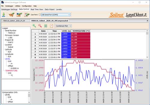
Figure 6-9 Viewing Compensated Files in the Data Control Tab


